


Company History:
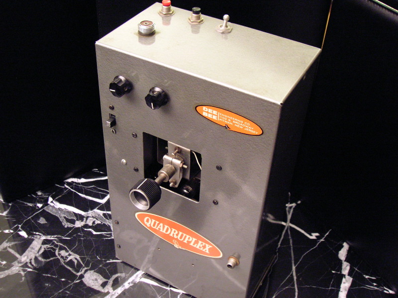
Quadruplex
Servo Started Everything
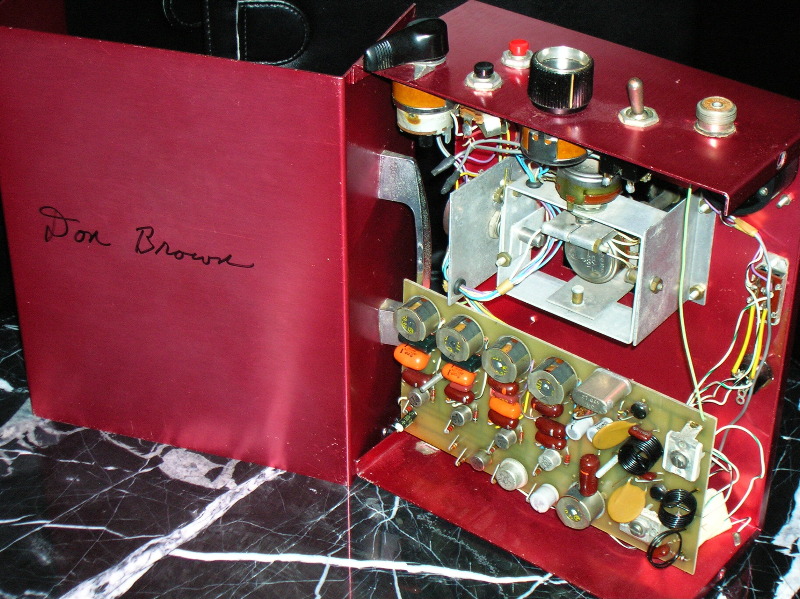
It all began with a servo. At first, this was Don Brown’s only product and it brought him together with electronics wiz Carl Schwab who would become Quadruplex’s chief designer. Quadruplex was manufactured by Dee Bee Engineering Co., which derived its name from Don Brown’s initials.
Around 1953, Don switched from single channel escapement control to a homemade mechanical pulser in a Rudder Bug and was a proportional fan from that day forward. In 1954, he developed a Galloping Ghost system which may have been the first. He called this the “crank system” and believed it predated by about one year the early Ghost system pioneered in Hampton, Virginia (by Nate Rambo and John Worth).
When visiting in the Los Angeles area, Don joined the famous LARKS R/C Club so he could fly in their contest. Despite winning the contest he was (like other proportional pioneers) teased and ridiculed by the RC establishment there. As the plane sat wriggling on the ground after each flight comments were made like “Don’t touch it – it ain’t dead yet” or “Stamp on it quick before it gets away”.
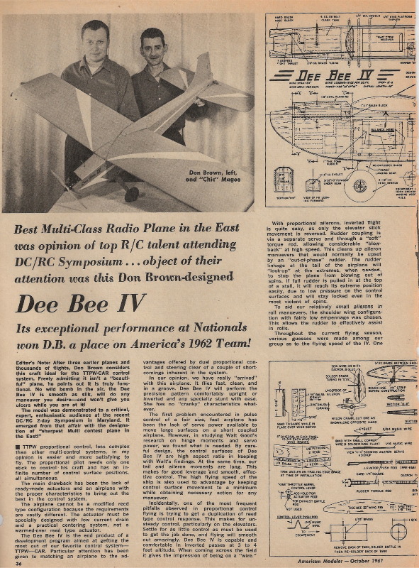
Don went on to win the 1957 NATS (Class 2) at Willow Grove, PA with this gyrating system. After this, he flew a Walt Good TTPW system for years and designed an airplane specifically for it called the DB. Don Brown demonstrated his plane and servos at the May 1961 DCRC Symposium. After Howard McEntee made some impressive low passes for the cameras with his plane, jaws dropped as:
“…Don Brown added thrills by making low, low, low inverted passes across the field with perfect timing and precision” -- July/Aug 61 G.L.
To accomplish this Don used his servo in his own design Dee Bee IV aircraft, controlled by a TTPW radio with coupled ailerons and rudder (CAR). This plane was specifically designed for this early proportional system and was capable of speeds approaching 100 mph and sustained inverted flight 3 to 4 feet off the ground as on a wire. Don noted that “with proportional ailerons, inverted flight is quite easy, as only the elevator stick movement is reversed”.
Using this same equipment Don Brown won second place in Multi at the 1961 Nationals in Philadelphia. This win generated considerable interest in the TTPW radio and DB IV airplane. American Modeler paid Don for an article on how to build a DB IV and he used this money to set up production of his new servos.
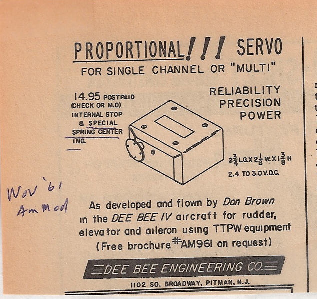
In the July, 1961 edition of American Modeler it was announced that Dee Bee Engineering Co. was entering the proportional servo field. These servos were designated model “T T” since they were designed for use with the early “TTPW” proportional system.
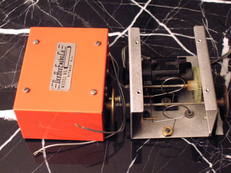
The new servo used a Mighty Midget motor with double reduction gearing to a ratio of about 50 to 1. But its highlight was the ingenious spring centering mechanism.
Carl Schwab noted that the initial spring rate near center was high and decreased as the physical deflection took place. The position that the servo took was a combination of this spring plus the blowback air load. Dee Bee claimed this 2 spring “Twin Tension” dual centering system provided a fairly smooth operating curve somewhat flattened around neutral to remove excessive control sensitivity found in other proportional systems when the stick is near center.
Here is an early ad for this servo, Nov. 61’ A.M., and a picture of one showing these unique centering springs.
 |  |  |
Don Brown’s Second Place finish at the 1961 Nationals earned him a place on the US team at the 1962 Internationals in England. There, he debuted the entire Quadruplex system and, as one commentator noted:
“…an immense amount of interest was shown in Don Brown’s Quadruplex proportional system, particularly in his servo, the details of which {the other contestants} busily copied into notebooks” – Dec 62’ M.A.N.”
It all began with the servo.
Carl Schwab Arrives
One of the spectators watching Don Brown fly his final round at the 1961 Nationals was an electrical engineer named Carl Schwab. Carl was surprised to see that direct pulse proportional systems could do so well. Back then, “bang bang” reed systems dominated and won multi competitions. Reeds nearly suffered a major loss that day.
As soon as he returned home to Huntington Station, NY, Carl Schwab wrote a letter to Don Brown explaining his interest in the Dee Bee servos and offering to provide a receiver design that would provide three pulse proportional channels with trimmable throttle. Don was preparing for the 1962 Internationals and badly wanted an improved radio with an additional channel. The Don Brown / Carl Schwab match was made, and they would forge ahead to write a large chapter of RC history. In Carl’s words:
“So we were off. I immediately dived into refining the design of a 3 tone system in which the on-off ratio of each of the three tones would control each of the three flight channels. Lee Berlette had a hand held version of the 2-channel feedback system and based upon what we had seen we decided to modify that to pulse proportional. Also, Andy Push was quite interested so I agreed to build a prototype system for him while I was building mine if he would scratch build a DB IV for me. All these systems including the one that Don was building were the so called MkI versions. All were slightly different but all did use the Dee Bee servos.”
By the time of the August 1962 Internationals the system had been tested and refined to the point that Don Brown and his friend Chick McGee were planning to go into production. It was decided that production Quadruplexes would be patterned very closely after Don Brown’s prototype. Carl Schwab agreed to consult on technical problems and improvements in exchange for a small royalty plus free production Quadruplexes for Carl’s own flying. Just one step remained.
Don hoped to score high at the upcoming Internationals with his prototype Quadruplex and ride a wave of free, favorable publicity to a successful product launch. He achieved his objective with a strong fifth place finish and came close, very close, to taking first. How close?? Just molecules away – molecules of glow fuel, that is.
At the 1962 Internationals, Don Brown was in first place with a commanding lead until his engine quit mid-flight. Were it not for that engine malfunction, radio control history would have probably been altered.
The Gas That Changed History
Don Brown’s engine failed twice that day in the 2nd and 3rd rounds of the competition. The press said his engine ran out of gas. Don attributes this fateful engine failure to his use of local (U.K.) fuel. He didn’t know that its different composition could cause clogging or otherwise lead to engine failure.
While the engine worked, his flights were so impressive and he racked up so many points, that he still won fifth place. This was a most remarkable accomplishment since it was achieved despite being unable to complete two rounds and receiving none of the possible points for each of the maneuvers which followed engine failure. Despite the great flying by Tom Brett (who ultimately won) and others with their reed systems, there can be little doubt but that Down Brown and his Quadruplex would have carried the day were it not for the engine failure.
What would this have meant? To put this in context, in August of 1962, Space Control was still striving for sales and Sampey had not yet introduced his 404. The Quadruplex system was exceptionally reliable and sold in relatively large numbers. It is difficult to predict how many more would have sold had he scored first in the internationals at a time when proportional was openly mocked by leading RC figures and not yet the heir apparent to the future of RC. The impact would have probably been quite large. The course of equipment development might have also been altered, for awhile at least, away from feedback systems and digital.
Here is a press account of one of Don’s flights that day:
“Once again the flight that everyone was now waiting for was Don Brown’s…Don went through half the pattern faultlessly and at maneuver no. 9, a roar went up from the crowd as he throttled back and his model performed the best and truest tail slide we had seen. Alas, when the noise of cheering and clapping died away, our worse fears were confirmed: the engine had stopped.”
Production Begins
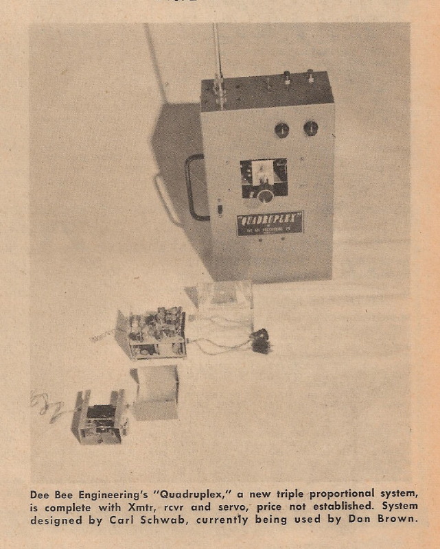
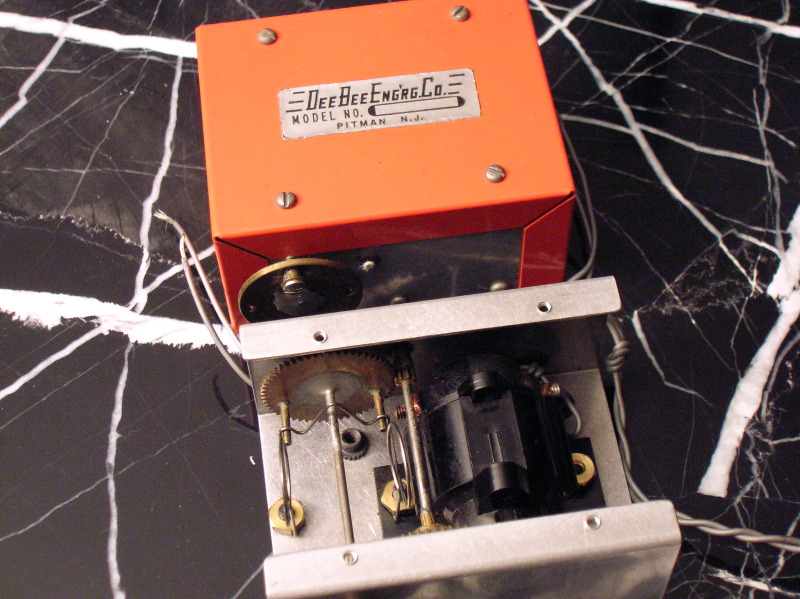
This photo was shot by Don Brown himself using his handmade prototype transmitter with a black rectangular “Quadruplex” label a friend made up for him. The friend evidently worked at a major corporation and had access to labeling and identification plaque apparatus. See Special Exhibits – The First Quadruplex, for additional information.
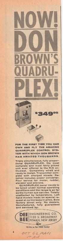
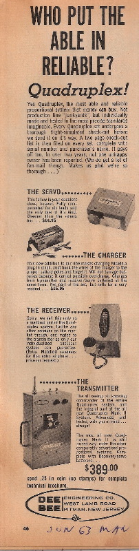
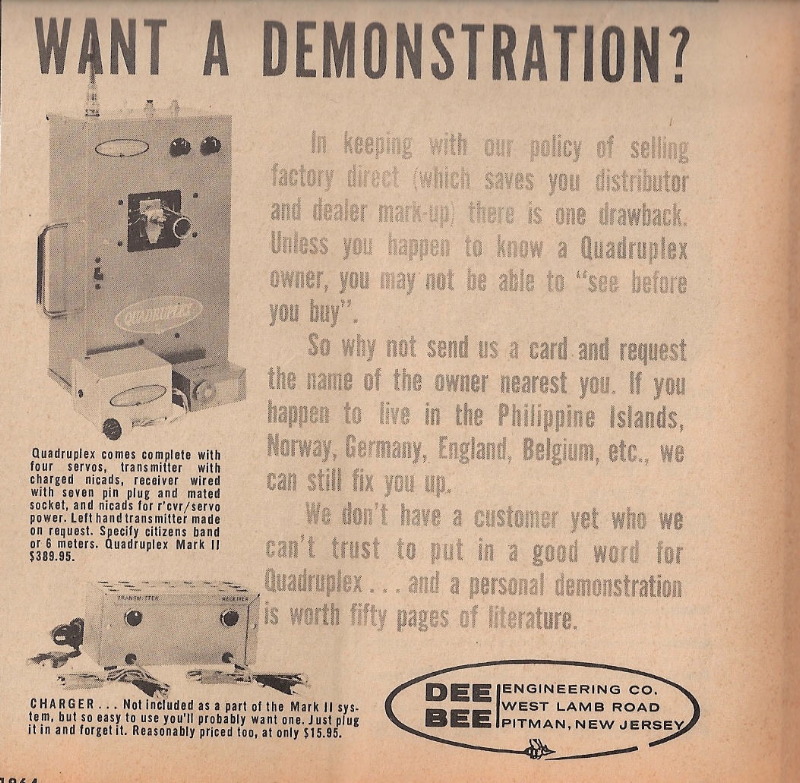
Emphasizing Reliability
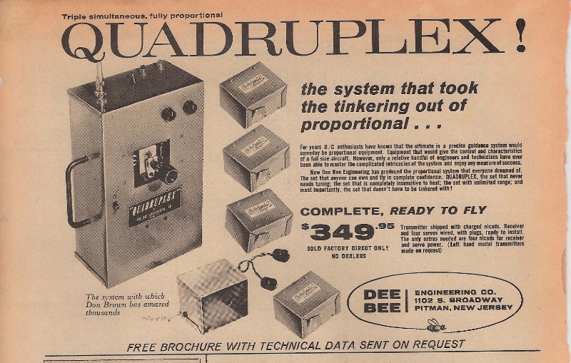
This ad stepped up the reliability point by touting the system as the one that doesn’t have to be tinkered with. This was an attempt to highlight Quadruplex’s advantage over both more expensive feedback systems (i.e. Space Control and Sampey) and less expensive TTPW and galloping ghost-type systems.
 |  |  |
New Location & Picture
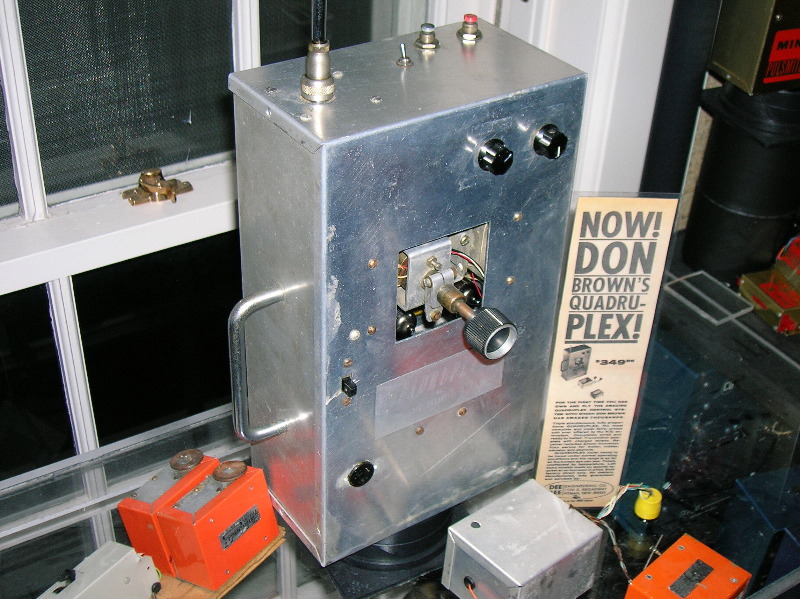
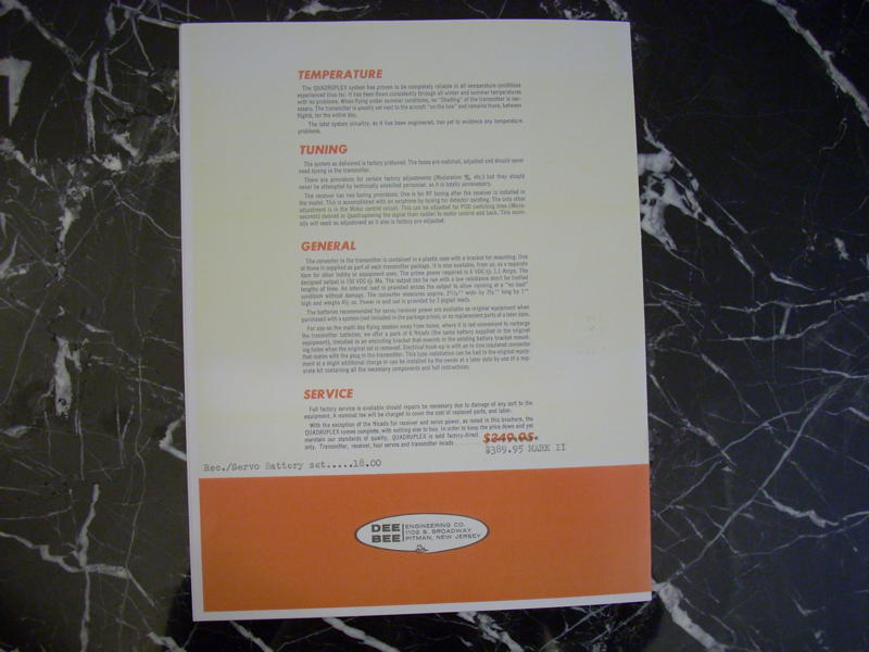
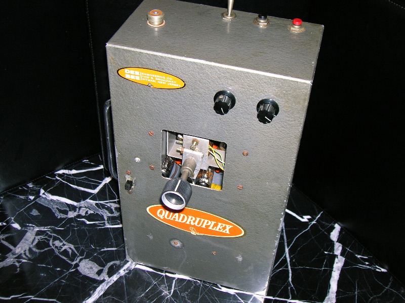
In the May/June edition of AM it was announced that Dee Bee Engineering Co. had moved to larger quarters and was increasing output of Quadruplex “multi propo apparatus.” In the June 1963 edition of M.A.N a new ad appeared. This advertisement showed an actual production transmitter for the first time instead of a picture of the prototype. It also listed the new West Lambs Road location and nailed the reliability and price themes.
There does appear to be one physical difference between the earliest and subsequent gray-case production Quadruplexes. The subsequent systems had one additional screw on the face of the transmitter. This is the “shiny” screw seen in the ad above the on-off switch screw. This held a voltage dropping resistor inside and indicates these later production transmitters had already switched from using a single 1.2 volt wet cell for power to using 2 NiCad wet cells with 2.4 volts. Charging jacks had not yet been installed on the front of such transmitters. Their batteries were charged by removing the back of the case, opening the vents on the cells, attaching the charger’s alligator clips and charging until a vigorous bubbling occurred.
Reliability vs. Purity
In the August 1963 M.A.N the authors described a visit to Dee Bee’s West Lambs Street facility. They were impressed with the test equipment and overall organization but mostly with reliability. They were surprised when Don Brown flew a system right off the shelf without so much as a range check and then, at altitude, retracted the antenna and continued to fly without problems. The two reporters were so impressed they chipped in 50-50 and bought one of the units on the spot. It is possible they only said this and were given a set for promotional purposes, but there is no doubt about Quadruplex’s reliability. It wasn’t the product of reporter’s spin or inflated product reviews so common today. It was real, it was widely recognized and it was big.
Until the CL5 version in 1965, Quadruplex’s nagging negative was its pulse rather than feedback technology. This produced a very slight jiggle or dither of the servo, a faint version of the older TTPW and galloping ghost gyrations. This was looked down upon by some as older, less sophisticated technology, not “pure” proportional, airborne battery draining technology and so on.
Supporters considered this disadvantage to be perceptual and to be far outweighed by the real advantages of price and dependability. They countered: What good is a “pure” state-of-the-art system if it cannot be depended on to bring your precious plane back in one piece, requires continuous tinkering and trips to the shop and costs more than most hobbyists can afford? This is a potent rebuttal and its persuasiveness and truth may be proven by the fact that (it appears) more Quadruplexes were sold than Space Control and Sampey combined. We are still researching to verify this, however. We aren’t picking favorites here. If you read our history of Space Control and Sampey you’ll see we are big fans of those systems too, and they were introduced substantially ahead of Quadruplex.
Feedback technology wasn’t necessarily more advanced. Carl Schwab had a working feedback proportional before he ever met Don Brown (although only 2 channels). Carl gave this up to develop the superior Quadruplex system. Perhaps the most compelling evidence in the historical record of Quadruplex’s superior reliability – something that approaches objective “proof” -- are the amazing RCM findings discussed in the “21” section below.
In fact, some believe it was a mistake when Quadruplex finally gave in to the incessant drumbeat about “pure feedback proportional” and produced the CL5. But we’re getting ahead of our story.
The next Quadruplex ad introduced an interesting comparison of component costs along with the usual price and reliability points. In addition, this ad was (admittedly) fixated on the advantage of single stick transmitters.
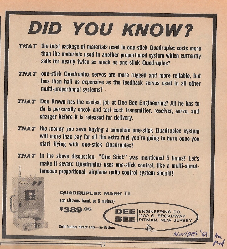
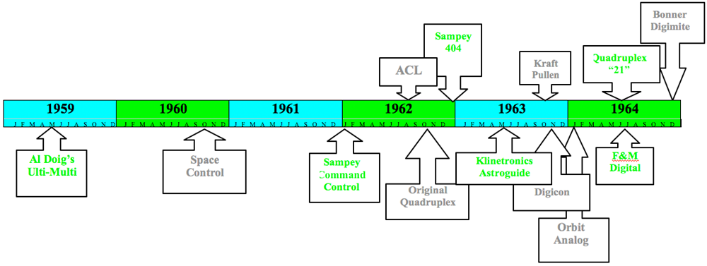
No mystery here. This was exactly the time that the first West Coast proportionals were introduced – the Kraft Pullen and the Digicon. Both of these competitors used a 2 stick transmitter, and the about-to-be-released Orbit proportional would offer both formats. Here’s the timeline for early proportional.
Early Proportional Timeline
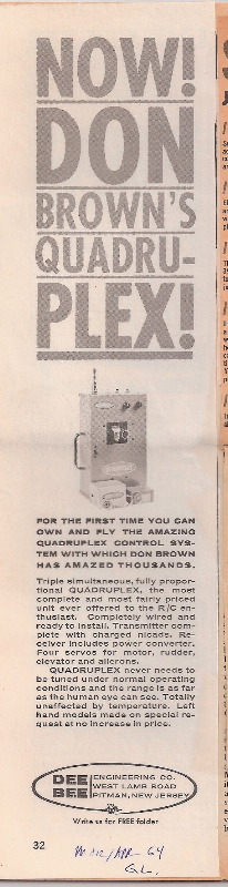
Distribution
Nomenclature
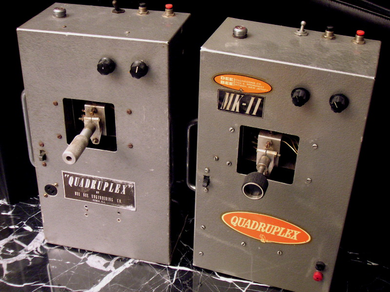
There is some confusion about the appearance of “Mark II” decal on some of the transmitters. This did not mean that it was a new more advanced version than earlier production models. All first production Quadruplexes (i.e. in the large, gray cases) were referred to by Quadruplex personnel as Mark II’s. They referred to the prototype phase as Mark I.
Since, as discussed above, there was one advance during Mark II production that involved external and internal differences, we refer to the earliest production units (single wet cell transmitter) as Mark II A and the later units (dual wet cell transmitter) as Mark II B.
Here’s how they looked:
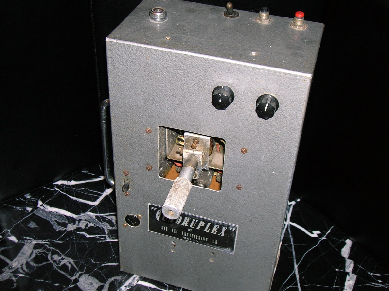 | 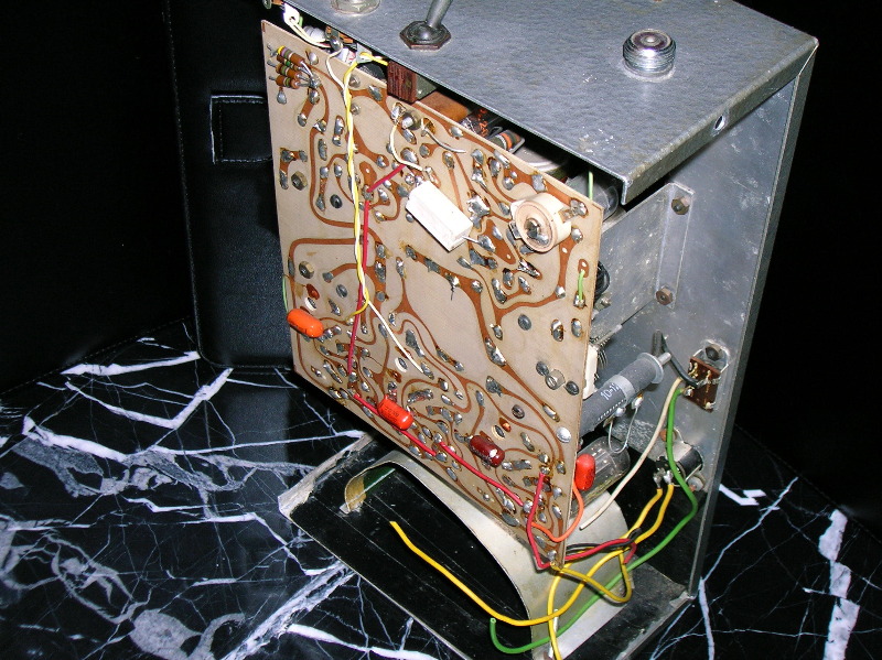 | 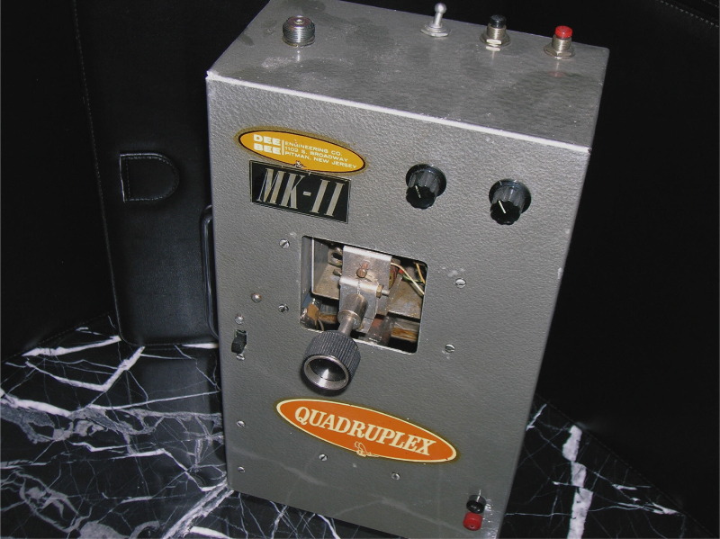 | 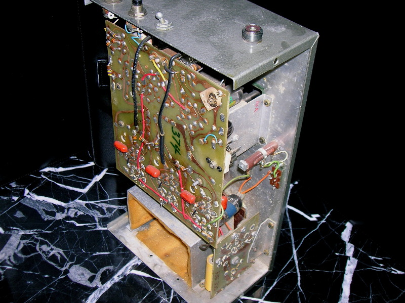 |
| MARK II A (voltage reducer retrofit to PC board) | MARK II B (original voltage reducer) | ||
 |  | ||
| LEFT HANDED (Mark II) | RARE MARK II NEVER RETROFITTED WITH CHARGING JACK | ||
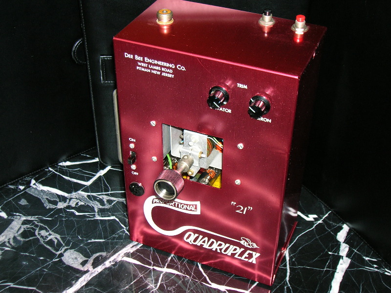
Quadruplex Turns “21”
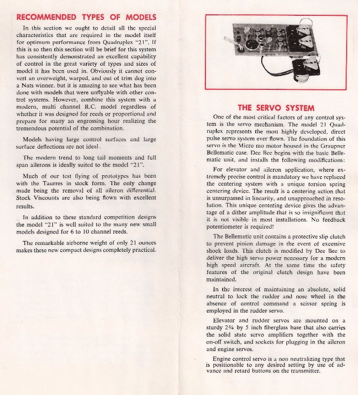
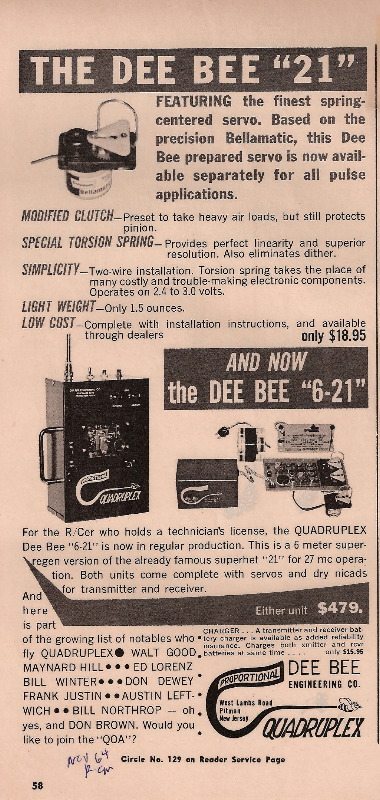
While Don Brown concentrated on manufacturing, Carl Schwab turned his attention to designing an improved system. His main objective was to eliminate receiver relays so that the receiver could be smaller and lighter. Next he modified Graupner Bellamatic spring - returned servos produced in Germany for reed systems.
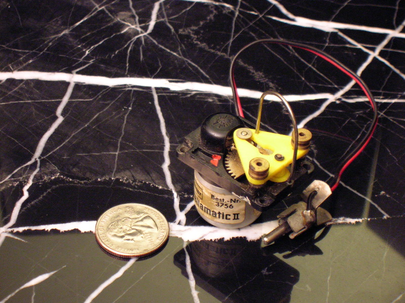
Becoming A Lightweight
First “21” Ads
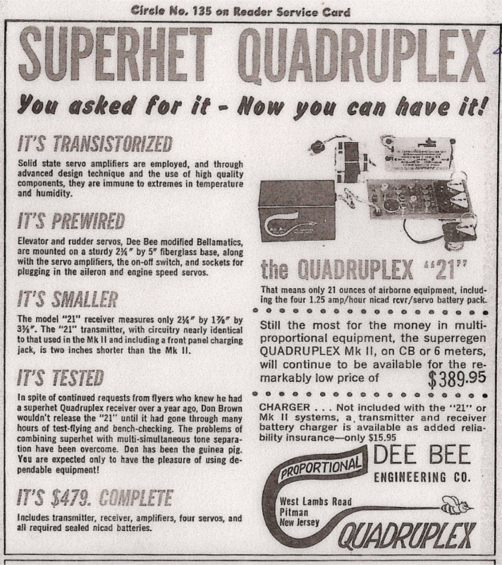
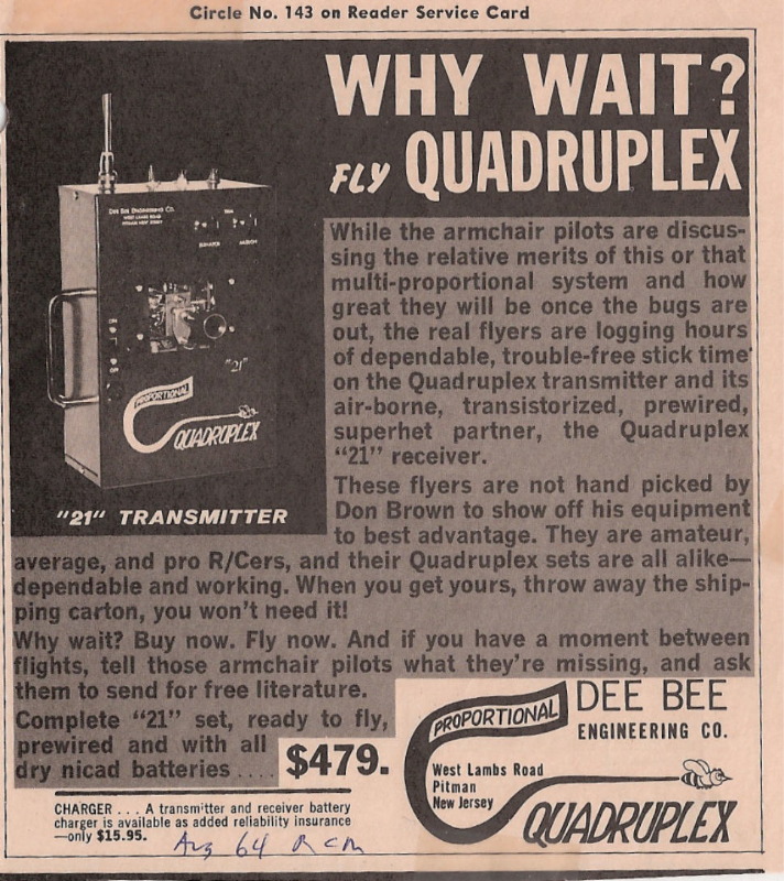
This ad returned to Quadruplex’s greatest strength – reliability. It poked fun at “armchair pilots” waiting for more advanced proportional systems. It even invited buyers to throw away their shipping cartons suggesting the notorious need to send early proportional systems back to the factory for repair and adjustment did not apply to Quadruplex.
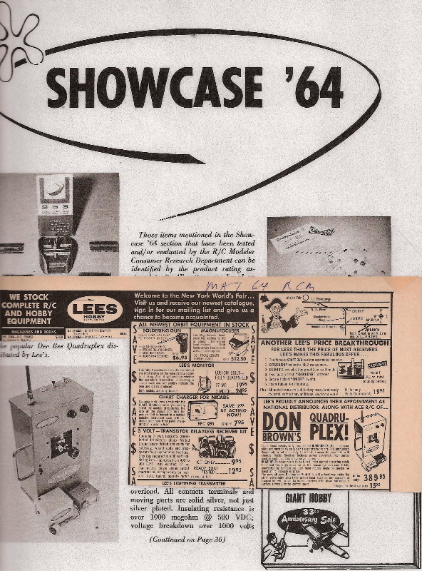
The Oct / Nov 64 Lee’s Hobby ad boasted that the “21” system makes full house proportional practical in an entirely new field of smaller aircraft designs such as Goldberg’s Falcon and Skylark. Thus, the “21” system with its hulking “red giant” transmitter may actually be viewed as one of the first in a long line of “mini and micro” RC systems, such as Cannon, which would grow in later years and continue to this day.
Proof Discovered
What happened next was truly remarkable and rarely found in historical records. A respected, neutral authority ran two clever, objective tests to determine which proportional system was most reliable and reluctantly reported the clear winner – Quadruplex. This comes as close to “proof” as you can ever hope to find and obviates the normal need to rely on subjective opinions from various individuals with differing perspectives and biases.
Radio Control Modeler (RCM) had quickly become the leading publication and authority on the RC branch of model aviation. As a West Coast organization RCM was steeped in West Coast influences and perspectives, and above any suspicion that it would ever be biased in favor of an East Coast system like Quadruplex. In its Sept 64 edition RCM described its proportional system challenge.
They contacted “virtually every proportional manufacturer from the early days of these systems” and received many promises that they would receive each manufacturer’s proportional rig to test and write up for RCM readers (free publicity). What happened next surprised and disturbed RCM. Despite all the promises and hype by leading RC manufacturers about their new proportional systems, only one manufacturer sent its system to RCM and “it was not one of the ‘Big Three’ – the gear we received was manufactured in the East by a gentlemen named Don Brown, and was one of his Dee Bee Quadruplex 21’s.”
RCM subjected the set to physical examination by 36 club members including “Heavy Handed Harry” but nothing came loose. They then test flew it and said the rumors were untrue that it was slow and that large control surfaces load the servos excessively; instead they found it “fun to fly and reliable to operate”. They did note the problem of high battery drain since the servos are “on all the time” and the risks of having the factory fail safe settings (what happens if the signal is lost) of low motor, full aileron and full up (e.g. disastrous to lose signal while inverted).
Thus Quadruplex won RCM’s proportional contest by default. The fact that the other systems didn’t even show up for a chance to garner free national publicity probably “spoke volumes” to RCM and its readers about them.
The second half of RCM’s “Quadruplex Reliability Proof” came in their October 1964 issue. This issue contained a detailed, formal review finding Quadruplex to be “a proven system, consistent in performance and reliability”. What was truly remarkable, however, is what accompanied this review. RCM disclosed that it had conducted a survey over several months seeking letters of comment from owners of all types of proportional. The results? For each proportional system “the pros and cons of a given rig were about equal”. Except for one.
“From scattered points throughout the world, this one system not only received more letters than any other, but in each case the report was all on the plus side of the ledger.”
******
…if it is possible for a manufacturer and his product to have a fan club the honors go to Don Brown and the Dee Bee Quadruplex “21”.”
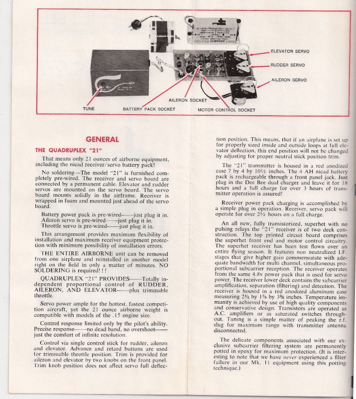
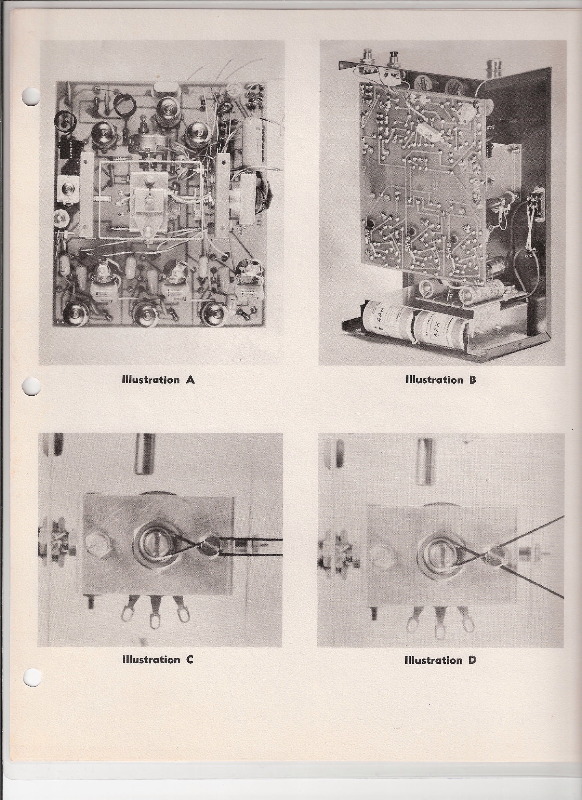
The review also mentioned that Dee Bee Engineering had grown to employ 6 full-time and two part-time workers and the 21 system won 2nd place in pylon at the 64’ nationals. RCM noted with approval how the installation of 21 systems was rendered easy by the integral servo circuit board, and that this reduced the risk of installation error and required no soldering.
During the flight testing RCM noted the slight quiver of the control surfaces is “barely noticeable” on the ground and appeared to make no difference in flight. Finally, RCM delivered its conclusion which couldn’t have been much more positive and directly addressed the common criticism that Quadruplex was less sophisticated and less “pure” than other proportionals:
“When we completed flight testing the Dee Bee Quadruplex “21”, we knew why the owners of this system were spontaneous, and in accord, with their praise of Don Brown’s product – it works, consistently and reliably. It is a system that the beginner to multi-channel will find much easier to handle than reeds. It will perform when you want it to perform. It will not have to go back to the factory for service after each few flights. We have heard it said that the “21” is not as exotic, or complex, design-wise, as some of the feedback systems. It is our feeling that this is exactly why its performance and consistent reliability is on such a high plane.
We like it, we fly it – and we recommend it to the RC’er who wants proportional control at a reasonable price, and with the assurance that it will perform consistently day in and day out.”
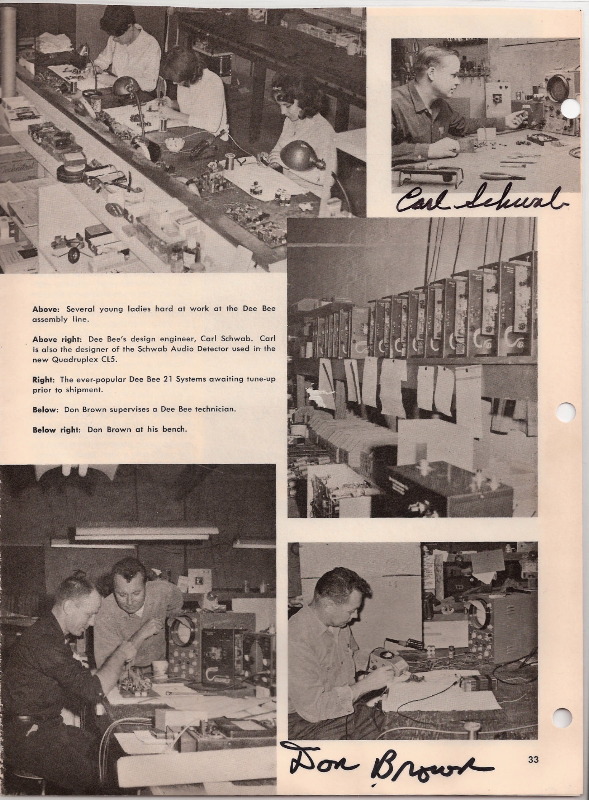
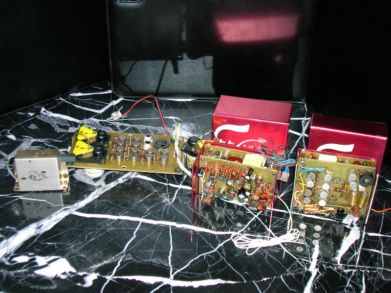
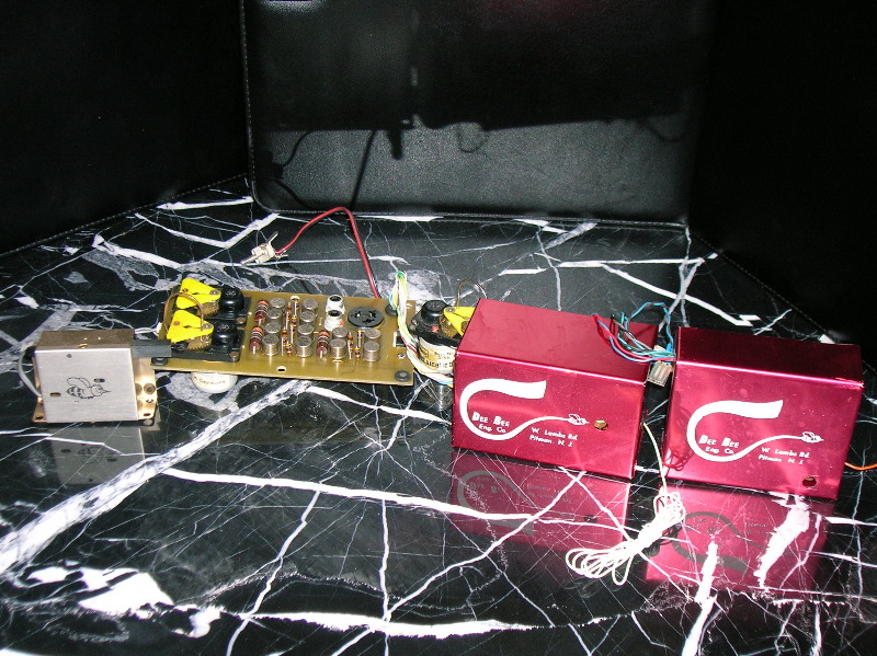
This “factory tour” was published in the July 65 RCM review of the later CL5 system. Although Carl Schwab is pictured with everyone else he actually was based at his house on Long Island and did not work at Quadruplex’s Pittman, N.J. factory.
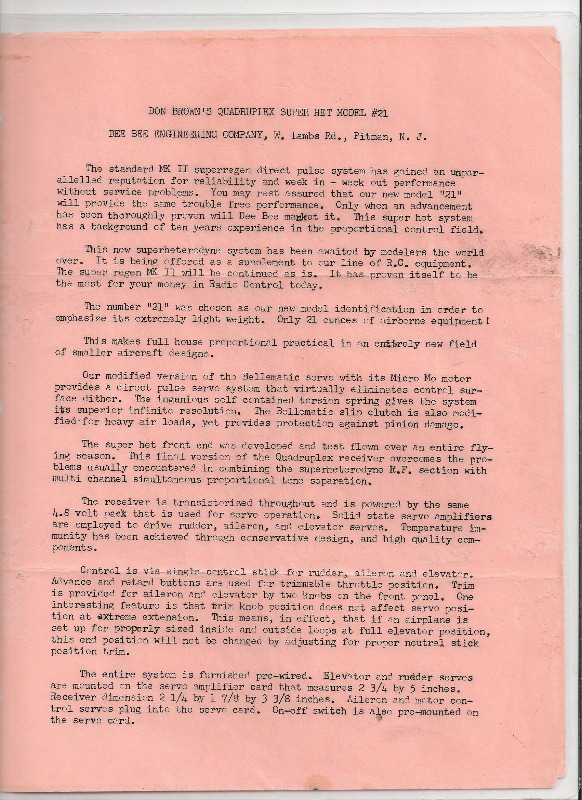
Additional Technical Information
By Carl Schwab, from Oct 64 RCM review.
The Quadruplex “21” provided completely independent proportional control of rudder, aileron and elevator, plus trimmable throttle. Servo power was adequate for the full house competition models, while the airborne weight allowed the use of the smaller .15-.19 size aircraft.
TRANSMITTER
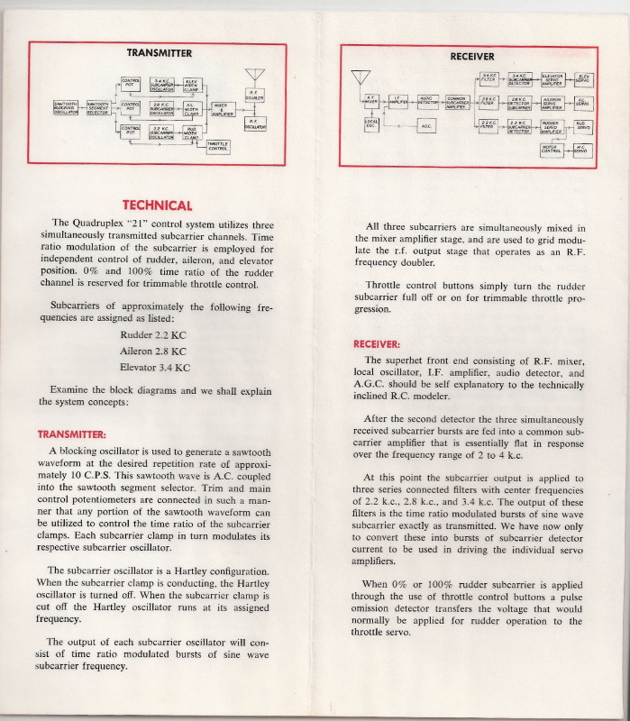
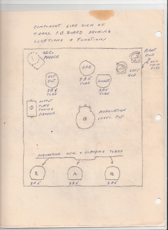
Three simultaneously transmitted subcarrier channels were employed by the Quadruplex “21” -- 2.2 KC for Rudder, 2.8 KC for aileron, and 3.4 KC for Elevator. Time ratio modulation of the subcarrier was employed for independent control of rudder, aileron, and elevator position. 0% and 100% time ratio of the rudder channel was reserved for trimmable throttle control.
A blocking oscillator was used to generate a sawtooth waveform at the desired repetition rate of approximately 10 CPS. This sawtooth wave was A.C. coupled into the sawtooth segment selector. Trim and main control potentiometers were connected in such a manner that any portion of the sawtooth waveform can be utilized to control the time ratio of the subcarrier clamps. Each subcarrier clamp in turn modulated its respective subcarrier oscillator.
The subcarrier oscillator was a Hartley configuration. When the subcarrier clamp was conducting, the Hartley oscillator was turned off. When the subcarrier clamp was cut off the Hartley oscillator ran at its assigned frequency.
The output of each subcarrier oscillator consisted of time ratio modulated bursts of sine wave subcarrier frequency. All three subcarriers were simultaneously mixed in the mixer amplifier stage, and were used to grid modulate the RF output stage that operated as an RF frequency doubler. Throttle control buttons simply turned the rudder subcarrier full off or on for trimmable throttle progression.
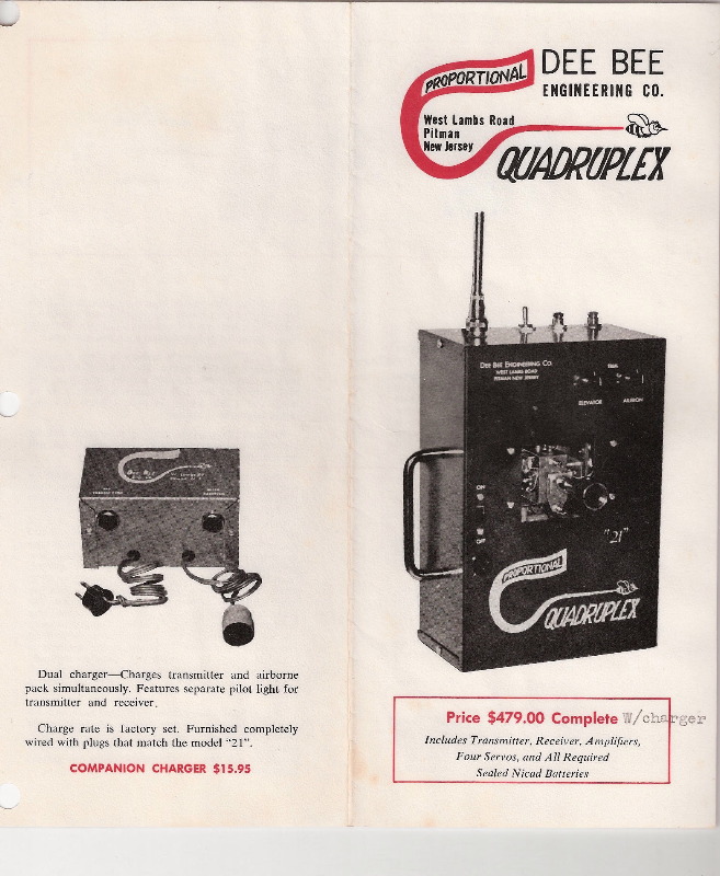
The transmitter itself was housed in a red anodized case measuring 10 1/2" high x 7” wide by 4” deep. The 4 amp hour nickel cadmium power supply was rechargeable through a front panel jack designed to accommodate the Dee Bee charger which charged the “21’ receiver and transmitter simultaneously. Eighteen hours of charge at the fixed charger rate assured over three hours of transmitter operation.
The “21” transmitter featured a single control stick for rudder aileron, and elevator. A red and a black button on top of the case advanced or retarded the trimmable throttle. Two small knobs above and to the right of the central control stick trimmed the aileron and elevator. The position of these trim knobs did not affect the full deflection position of the servos.
One additional feature on this particular model was a switch, located next to the throttle buttons, which allowed the rudder and ailerons to be coupled for those maneuvers or portions of the pattern where such a feature would be advantageous.
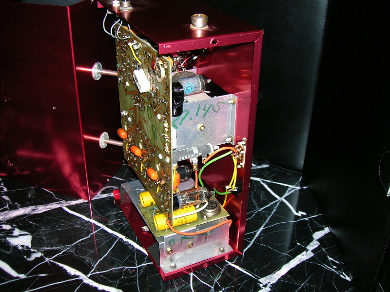
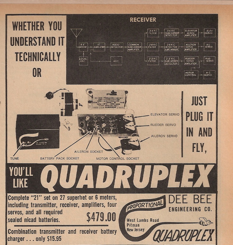
RECEIVER
The superheterodyne receiver utilized in the airborne system was a two-deck, fully transistorized unit with no pulsing relays. The upper printed circuit board comprised the superhet front end, consisting of RF mixer, local oscillator, IF amplifier, audio detector, and AGC, along with the motor control circuitry. The lower deck contained the subcarrier amplification, separation (filtering) and detection stages. After the second detector, the three simultaneously received subcarrier bursts were fed into a common subcarrier that was essentially flat in response over the frequency range of 2 to 4 KC. At this point, the subcarrier output was applied to three series connected filters with center frequencies of 2.2 KC, 2.8 KC, 3.4 KC. The output of these filters was the time ratio modulated bursts of sine wave subcarrier exactly as transmitted. These were converted into bursts of subcarrier detector current to be used in driving the individual servo amplifiers.
When 0% or 100% rudder subcarrier was applied through the use of the throttle control buttons, as mentioned, a pulse omission detector transferred the voltage that would normally be applied for rudder operation to the throttle servo.
Tuning the “21” receiver was a simple matter of removing the transmitter antenna, and while holding the ship four feet or more above the ground, peaking the RF slug for maximum range (about 10 to 20 feet).
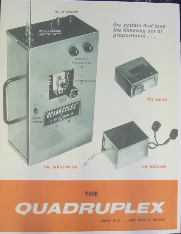
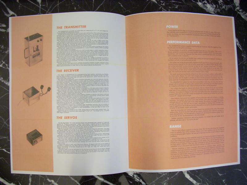
Here are the brochure and operating instructions for the Quadruplex “21”:
 |  |  |  |  | 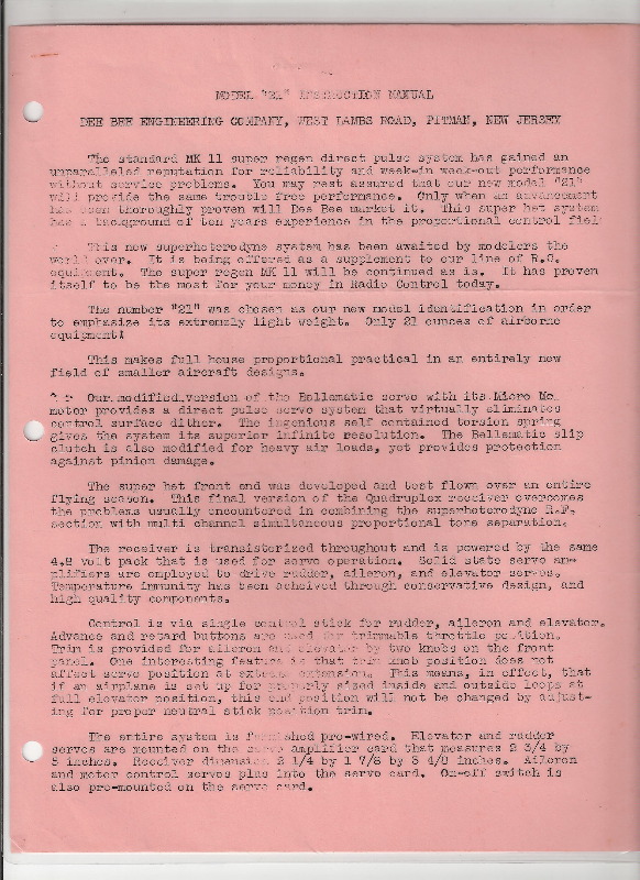 | 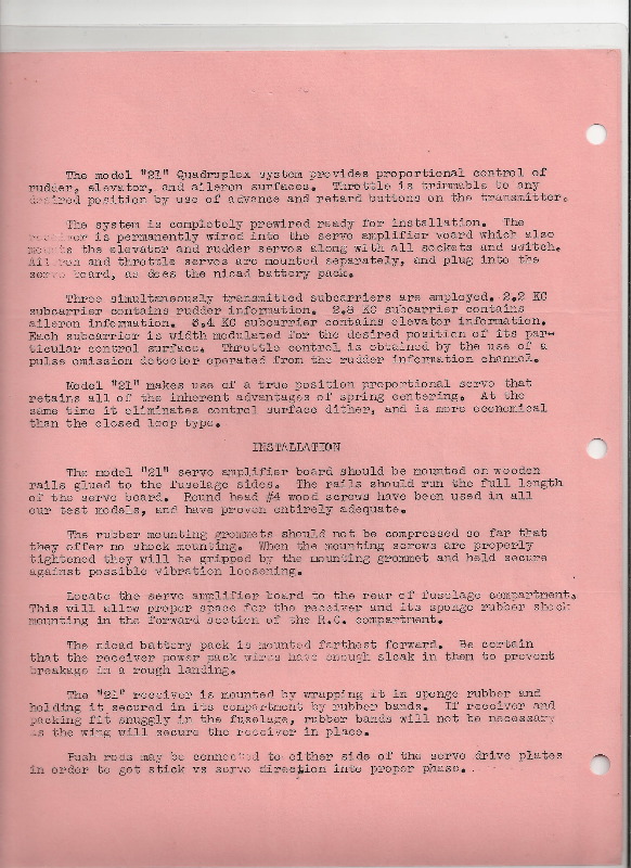 | 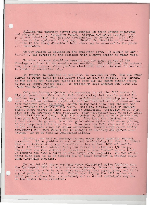 | 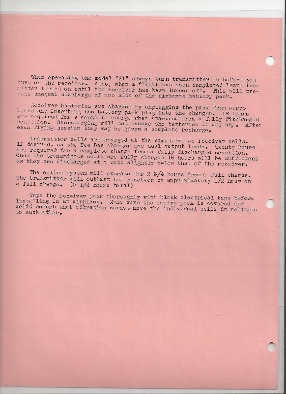 |
Here are first pages of the initial and later, more refined, service manuals, for comparative proposes:
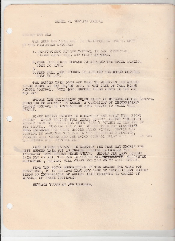 | 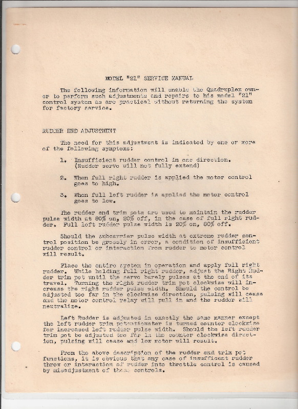 |
Kits And Mods
In the April 1965 MAN, Don Brown announced that he would begin selling Quadruplex “21” systems in kit form for about $100 less (i.e. $379 vs. $479). This move was designed to expand sales by tapping into the lower budget market. By Sept 1965 the kit price was dropped another $80 to $299.
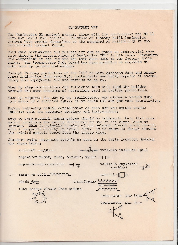
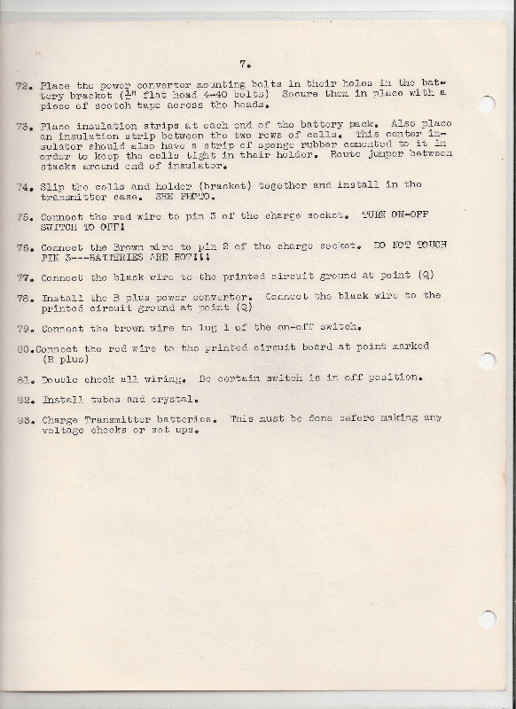
The kit was designed to be assembled by modelers without electronics expertise using only common tools such as a soldering gun and pliers. The lone exception was the need to own or borrow an oscilloscope. To further lure budget – oriented and cautious customers, Don Brown would sell the instructions alone so prospects could test the water and learn exactly what was involved first, and then Don would deduct this instruction cost from the price of the kit for anyone who took the next step.
Here’s how the kit instructions looked (selected pages):
 |  |  |
 |  |
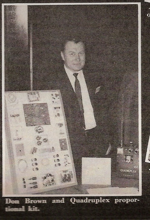
Here’s a photo of Don Brown at the 1965 Toledo trade show, promoting the “21” kit.
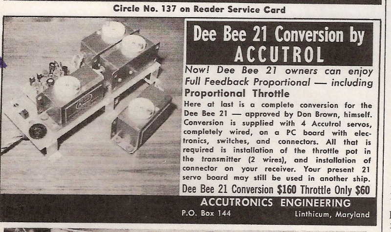
In the [Sept / Oct 65] edition of A.M. Dee Bee published instructions for adding full proportional throttle control to the “21”, instead of its trimmable motor control. This resulted in a completely additional function using a feedback servo, allowing the standard “21” motor servo and transmitter buttons to become an auxiliary control. Significant modification of the transmitter and receiver was required for this so Dee Bee offered the option of having the mod factory installed for $60. The recommended servo was Accutrol, indicating that Don Brown had already established a relationship with Bernie Murphy whose Accutronics company would make the servos for the next and final Quadruplex – the CL5.
Knight In Armor
CL5 Comes Alive
The Quadruplex “21” modification kits reflected the incessant pressure on Don Brown to produce a “pure” feedback proportional system without servo dithering. Carl Schwab recalls that Don was extremely anxious to produce a feedback servo system as “people were deviling him about when they could get one”. Carl recalls “You never had to apologize to a modeler after he test flew [the reliable Quadruplex]…but there was the constant gripe “but it ain’t true proportional”.
In addition, Space Control, ACL and Klinetronics had long-offered a fourth fully proportional channel for motor control and new systems like Digicon, Orbit, Kraft-Pullen and F&M were coming out, increasing the competitive pressure. After attending the 1964 DCRC symposium at which Bob Elliot described his upcoming digital system (EK Logictrol) and rumors swirled about Bonner’s forthcoming 8 channel digital, Carl Schwab knew it was time to develop an all-new Quadruplex.
“Eureka” Moment
Carl’s quest for something new took him back to what he had engineered years earlier – feedback proportional. Only this time there would have to be more channels and better performance all around, given the march of technology over the past 2 years. The breakthrough design came to Carl Schwab one night in a classic “Eureka” moment.
One of Carl’s projects in his ‘day job” was designing telephone modems that enabled 18 parallel teletype channels to be transmitted over a single telephone channel. Any input signal leakage through the phase detector would produce a phenomenon known as “entraining” which caused erratic operation. Carl became expert at detecting and preventing “entraining. With this expertise, Carl tried 3 different design approaches for feedback proportional; but all proved to be too cumbersome, complex and costly to produce. Then, it dawned on Carl that he could harness the normally undesirable “entraining” phenomenon to produce excellent feedback proportional, effectively making lemonade out of lemons:
“Suddenly the light lit! Why not build a frequency discriminator controlling this “entraining” and produce an error signal that could drive any analog servo.
****
Everything got simpler and standard servos such as Bernie Murphy’s worked well” - Carl Schwab
Carl found he could deliberately inject signal into the receiver and control the resulting “entraining” to produce a frequency detector. This produced five advantages:
1. The Phase Detector (PD) became nearly trivial because “entraining” was now controlled and useful.
2. The Voltage Controlled Oscillator (VCO) no longer needed a tuning device.
3. The amplifier was no longer needed at all.
4. The PD, VCO tuning device and amplifier became “extra stuff” which no longer needed to be packaged for each channel.
5. They could now use the best available “off the shelf” servos.
The slimmed down circuit became ILOD or “Schwab detector”.
Transmitter
[Substantial portions of the following paragraphs are from RCM’s July 1965 review.] Carl engineered a fully transistorized transmitter (a first for Quadruplex) that sent four simultaneous tones. Don Brown designed all the physical parts of the transmitter, including a beautiful new machined control stick. RCM found this made single stick control much more positive as it allowed the flyer to “rest his hand on the transmitter case holding the stick as he would a pencil, giving very precise fingertip control”.
The redesigned transmitter was 8 5/8” x 7” x 3 ¼”, substantially smaller than its predecessors. Since there was no need to pulse or commutate the tones, the number of internal components was greatly reduced. Only eight transistors were used. The red anodized case carried forward the Quadruplex look “although considerably smaller and more refined”. RCM noted that “inside there is no resemblance to the earlier systems except for the high quality workmanship”.
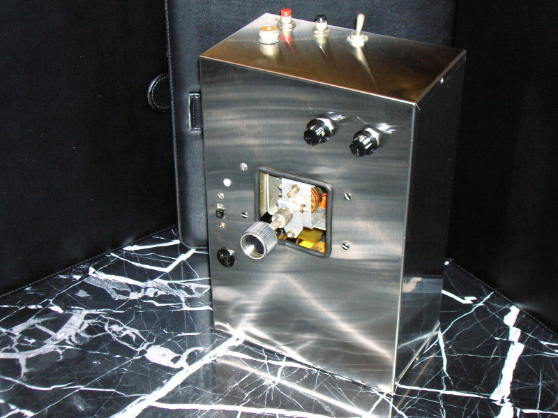
Here’s how the CL5 transmitter looked: this one was Don Brown’s personal CL5 (see “Last Quadruplex” in Special Exhibits)
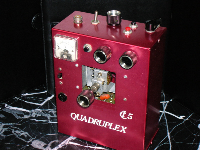 |  |
In addition to the control stick the front of the transmitter had rudder and aileron trim knobs, a charging jack under the on-off switch like “21”, and a dual purpose meter indicating RF output plus, if the adjacent red button were depressed, battery strength. On the top of the transmitter were throttle control (the right corner pointer knob), elevator trim knob (controlled by the left hand during flight), and red and black buttons to operate a fifth, auxiliary, control (e.g. brakes, flaps or retracts).
Receiver
The receiver had 2 decks. The upper was the superhet “front end”. The lower contained 4 “Schwab Detectors” named after their famous designer, Carl Schwab. These separated the four simultaneous tones received from the transmitter and directed them to the proper servos. RCM was “amazed” to see on an oscilloscope how the Schwab Detectors worked. Each Detector created a tone in the receiver, one for each of the four core functions:
“The receiver locks on to the transmitter tone, and any slight variation from the transmitter will cause the receiver to follow. The receiver and transmitter act very much like magnets in that the receiver almost attracts the transmitter tones. With any incoming signal from the transmitter, the signal output to the servo is constant with no degrading of control with extreme distance. With any loss of the transmitter, the receiver will return to its own neutral.”
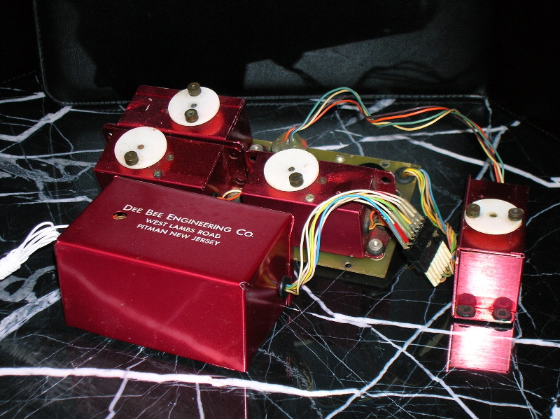
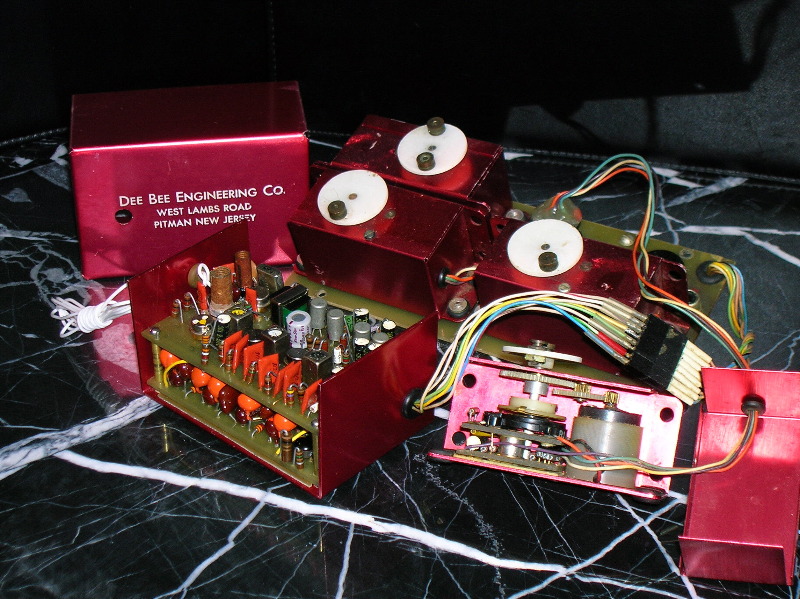
Servos
CL5 system servos were made by Accutronics. After initial production runs, Carl Schwab believes Don Brown bought a complete set of production machinery and made the servos at Dee Bee, paying a royalty or other agreed charge to Accutronics. The normal Quadruplex-red anodized aluminum was substituted for Accutrol green on the servo cases. The servo used the Siemens/Falhauber motor which had the first gear pass inside the motor case.
Reliability Redux
RCM praised Dee Bee for coming out with an entirely new system instead of taking the easy path of building a sequel to the successful “21” by merely modifying it to feedback plus proportional throttle. RCM’s tests showed CL5 to perform “as well or better than the manufacturer had indicated”, and RCM said “it is our general feeling that the new CL5 system may well prove even more reliable than its “21” predecessor, in as much as there are no relays, no tubes, and generally fewer components than these earlier models”.
RCM found CL5 to be “exceptionally interference free.” One of their bench tests was extraordinary. They switched on other transmitters, both proportional and reed, on the same frequency, but there was no effect on the CL5!
Full control was maintained under all conditions. RCM thought this was due to the receiver design and “its ability to separate independent tones and recognize only those four with which it is concerned, rejecting all others”. This sounds something like the description of the revolutionary “spectrum” and other 2.4 GHz radios which appeared 40 years later. Carl Schwab’s amazing Schwab Detectors upheld the reliability honors of Quadruplex for another generation.
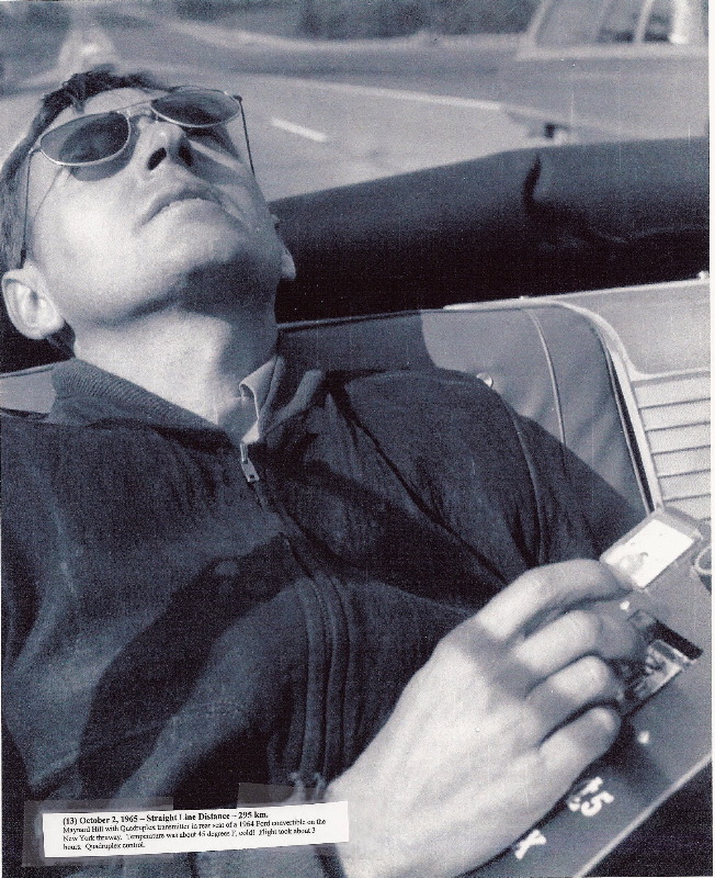
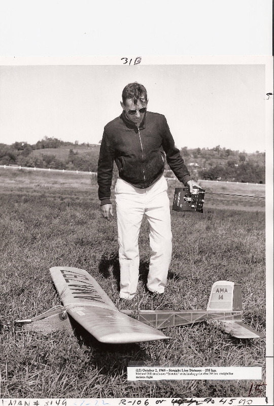
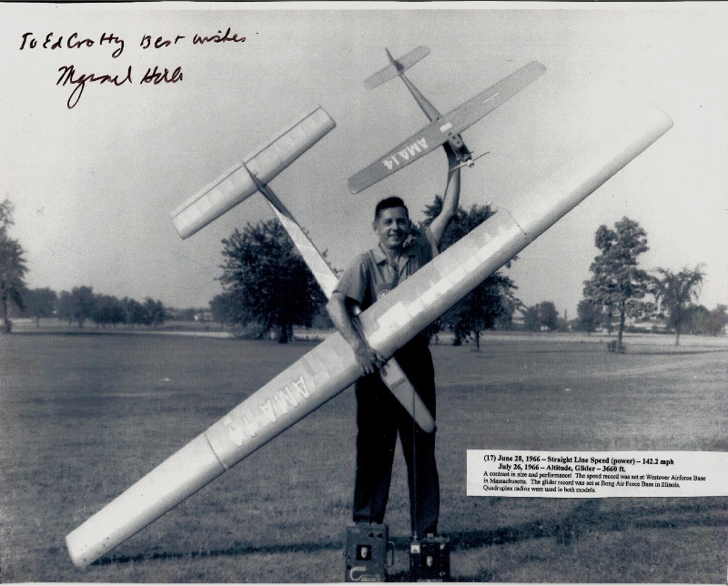
Maynard Hill complimented the reliability of the CL5 as he used the system to set several world records. One of these, the distance record, involved him riding in the back seat of a convertible flying his model while the car was driven 183 miles down the New York State Freeway. He said he never lost control or suffered glitches even when passing under bridges, high tension wires, trees or other obstructions.
Negatives
All pioneering systems had their minuses and trade-offs. CL5 was no exception:
- CL5’s airborne components weighed 25 ½ ounces, a 4 ½ ounce worsening compared to “21”. This 21% increase in the highly important airborne weight was a major step backwards. However it was offset in part by the ability of the more powerful CL5 servos to handle larger and faster planes.
- At $579, CL5’s price also increased substantially, from $349 for the first Quadruplexes and $479 for the “21” systems. This hefty price tag removed Quadruplex from the relatively affordable category and burdened its ability to compete against the burgeoning ranks of attractive competitor systems. These included the Logictrol 7 channel ($495), F&M Digital Five ($439 - $539), Bonner Digimite 8 CH ($615), and Micro-Avionics five channel ($395).
- CL5 suffered control shifting if the temperature difference between the receiver and transmitter exceeded 30F. How serious could this have been, given that Maynard Hill set a world altitude record (Glider) with the CL5? In addition, at 100F the maximum throw of the servos in each direction was reduced.
- Wearing on the feedback pot element near center (particularly on elevator) was another problem. However, nearly all early proportionals, analog or digital, had this problem until years later when the Cermet pot became available.
- RCM considered the antenna “a little awkward, due to its extreme collapsed length”, and missed the “convenient handle” which came with earlier Quadruplexes.
Advertising
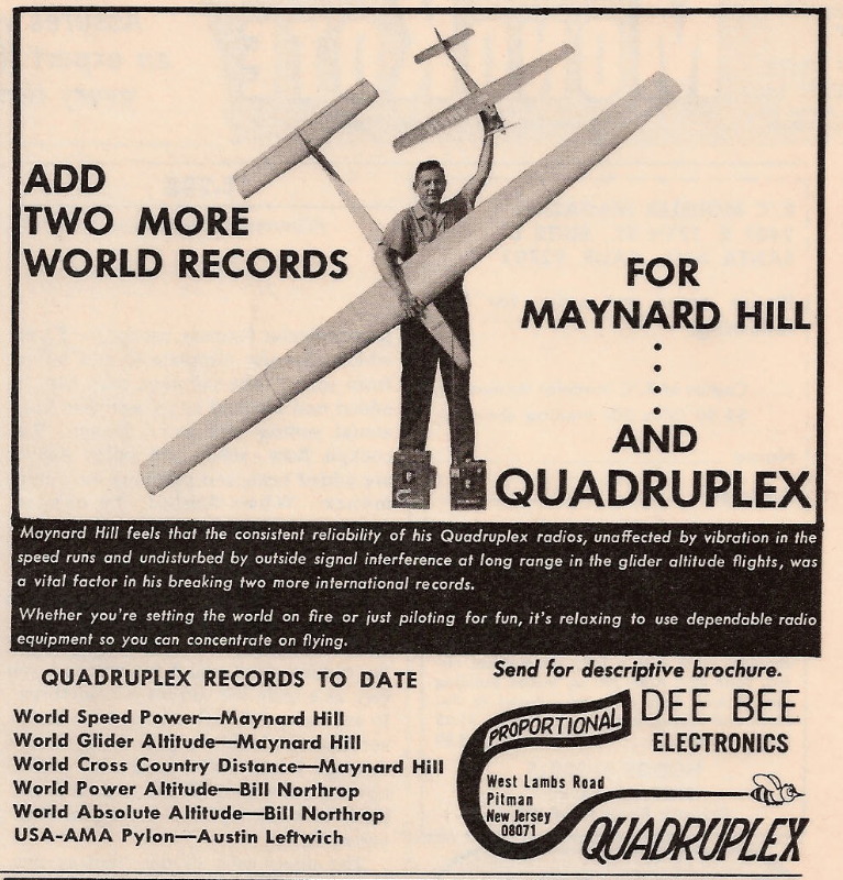
This ad ran periodically from around August 1965 until August 1966. Not a single word was changed in this ad throughout this entire period.
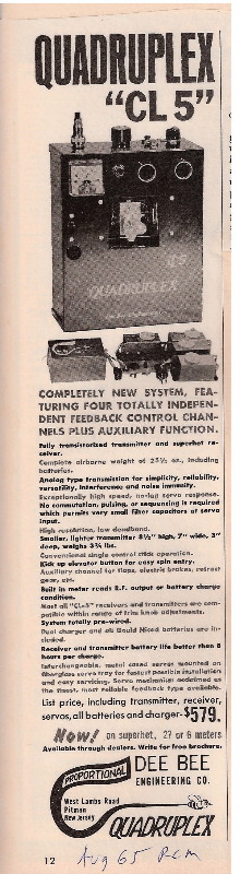
Quadruplex – World’s Record
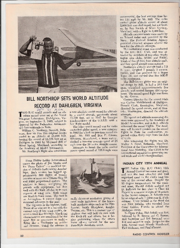
Not many RC systems can claim to have set official world’s records. Quadruplex earned many. On September 5, 1965 Bill Northrop beat Maynard Hills’ Sampey 404 world altitude record (13,328 feet, 1963) by reaching 16,690 feet. The straight line distance to his plane at its apogee was over 3 ½ miles. To accomplish this, Northrop needed an extremely reliable and powerful long-range radio. He used Quadruplex, but which one? The state-of-the-art CL5?
Wrong. The previous generation Quadruplex “21”?
Wrong again. Northrop used the first production model Quadruplex – the MK II or “Big Gray Box”.
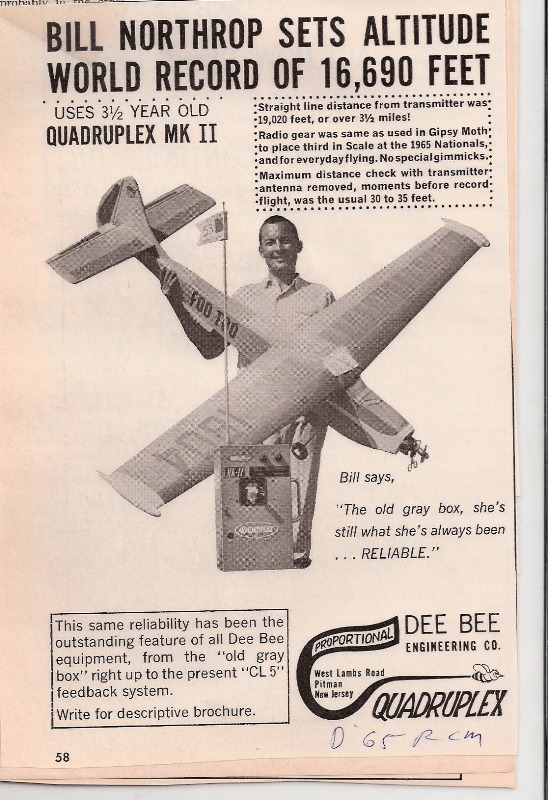
Note how the ad quotes Bill Northrop as saying “The old gray box, she’s still what she’s always been…RELIABLE”. One of the most powerful advertising techniques is to state a simple, towering truth.
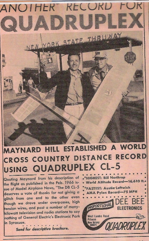
On October 2, 1965 with permission from Governor Rockefeller to use the New York State Throughway. Maynard Hill set the world distance record (183 miles) using his CL5. Here are the initial pages of the February 1966 MAN article on this feat:
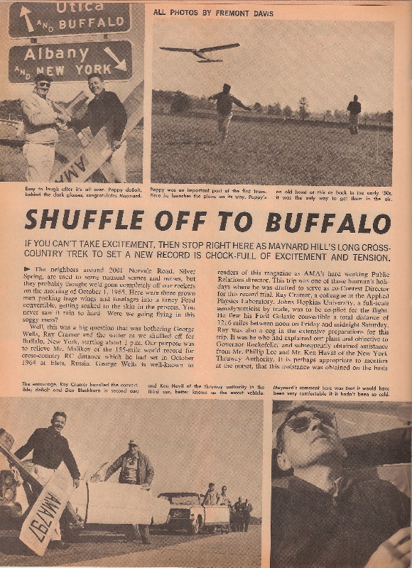
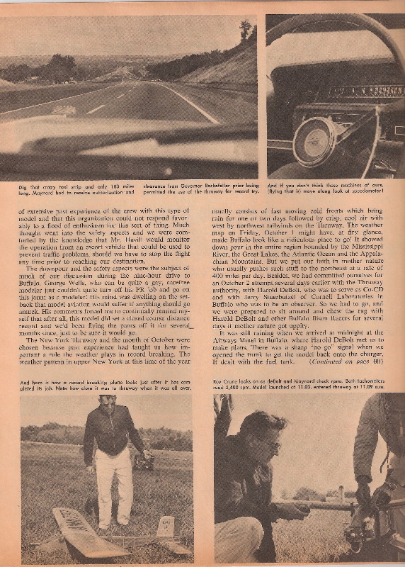
In this article, Hill said the “DB CL5 deserves a vote of thanks” for not giving a glitch from one end to the other despite driving under overpasses, toll plaza roofs, high tension wires and “past a number of many kilowatt television and radio stations to say nothing of General Electric’s Electronic Park in Syracuse.”
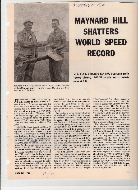
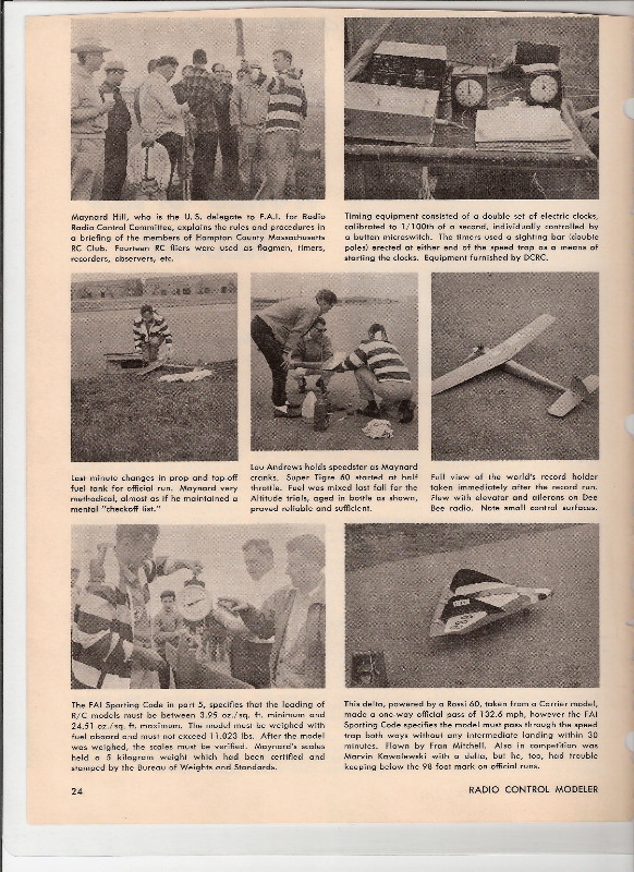
On June 26, 1966 Maynard Hill broke the World Speed Record using his Quadruplex 21. Here is the October 1966 RCM article about this feat:
 |  |
In the April, 1967 edition of FM, Maynard Hill explained he deliberately chose the “21” system for the speed record attempt because of its spring-centered servos. He said spring-centered servos enable smoother, more accurate flight with more “feel” to the stick since they produce torque in proportion to stick motion. This produces smooth corrections rather than abrupt jerks when the stick must be moved radically for emergency situations at high speed. He believed this outweighed the disadvantage of high current draw and battery drain since speed flying was “nothing but a continuous string of emergency situations”.
Competitors Surge
During CL5’s 1st year, the competition went from tough (noted under “Negatives” above) to virtually unbeatable. Newer, lighter “digital” systems kept appearing and then, in February 1966, the bottom dropped out of the market.
Kraft affiliate PCS introduced its 5 channel digital system for the revolutionary price of $299.95. The arrival of PCS was an R/C earthquake sending shockwaves throughout the industry. As another leading manufacturer said, “the handwriting was on the wall”.
Don Brown thought it was time to move on. He decided to produce ARF’s, one of the first to do so, while continuing to service his loyal Quadruplex customer base.
Additional CL5 Information
By: Carl Schwab
The CL5 was the last of the Quadruplex line. Many, many hundreds were sold and used well into the 70’s. The CL5 was pure FDMA, 4 subcarriers were generated and sent continuously and simultaneously. The subcarrier frequencies used were Aileron, 1690Hz, Rudder, 2140Hz, Elevator, 2600Hz and Throttle 3090Hz. Principle difference from Doig’s Ulti-Multi were that the CL5 used 1-coil ratio detectors hence did NOT have to use hard limiting in the receiver (big source for intermod signals). The 1-coil ratio detector can also be termed an ILOD, meaning Injection Locked Oscillating Detector. Don didn’t like either of these names so he just called it the Schwab detector. Anyway Don did a great job packaging the CL5 and added a couple of features the customers really like. First he had the throttle channel do double duty to drive an auxiliary circuit at low throttle which conveniently drove Walt Good’s electric brake. This worked great on taxi maneuvers; set the low throttle for comfortable taxi speed and by simply pressing the brake button the throttle drops to dead low and brake applies. Release the button and throttle resumes the taxi setting etc. The second feature he added was the extra UP elevator button which made spin entry dead simple.
The servo design used with the production CL5 was the Accutrol designed by Bernie Murphy. These units were temperature compensated and used the Micro Mo motor. Units stood up well. Some CL5s were supplied with Phelps Analog servos and a few with Steeb Atlas servos.
The CL5 was fully transistorized; some silicon and mostly germanium. Because it was obvious that silicon was the choice of the future I put considerable effort into siliconizing the superhet and the amplifier-soft limiter section. And of course the transmitter circuits as well. The most meaningful improvement was the use of the Siemens coil/cap combinations which tracked over a -40C to +55C temperature range. Siemens had invested millions of $ to get a strong position in the telephone frequency division multiplex equipment business where the wide temperature range was a must. For us the big gain was the coil used an adjusting slug that let you vary the inductance value +- 5%. For manufacturing this was great – cutting setup time drastically.
