
Special Exhibit:
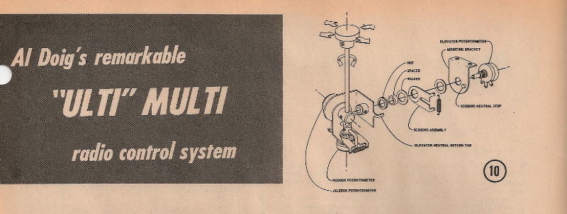
First Proportional? Doig’s Ulti Multi
(Click on any of the images on this page to see a larger version)
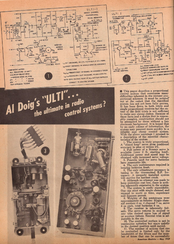
This is Al Doig’s “Ulti” Multi. It was a full-house, closed-loop, feedback, non-wiggling, multi proportional system said to “overcome many difficulties inherent in the pioneer proportional schemes”.
The Ulti Multi was revealed to the modeling world in May 1959.
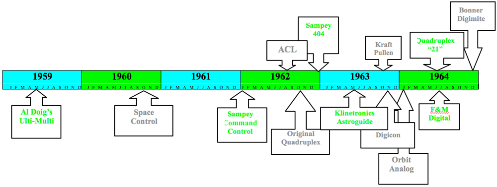
That’s right 1959! A full year ahead of the first commercially–available proportional, Space Control. To put this in perspective, here’s the timeline for early proportional.
Early Proportional Timeline
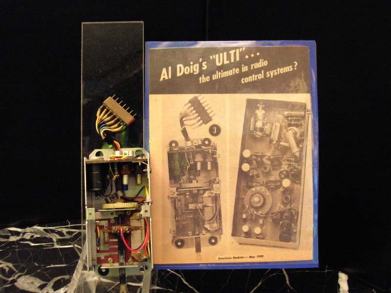
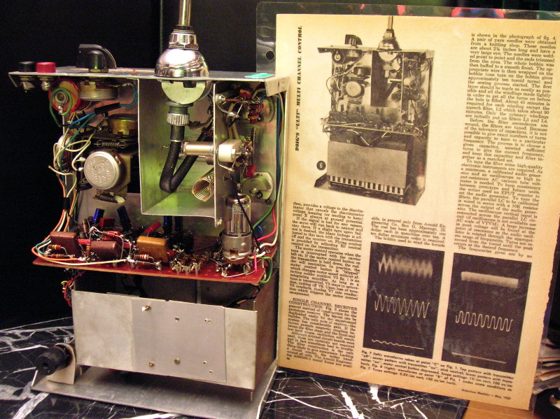
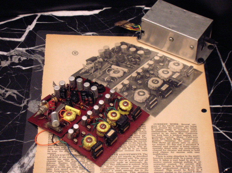
Here’s how the historic American Modeler article looked:
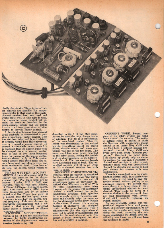
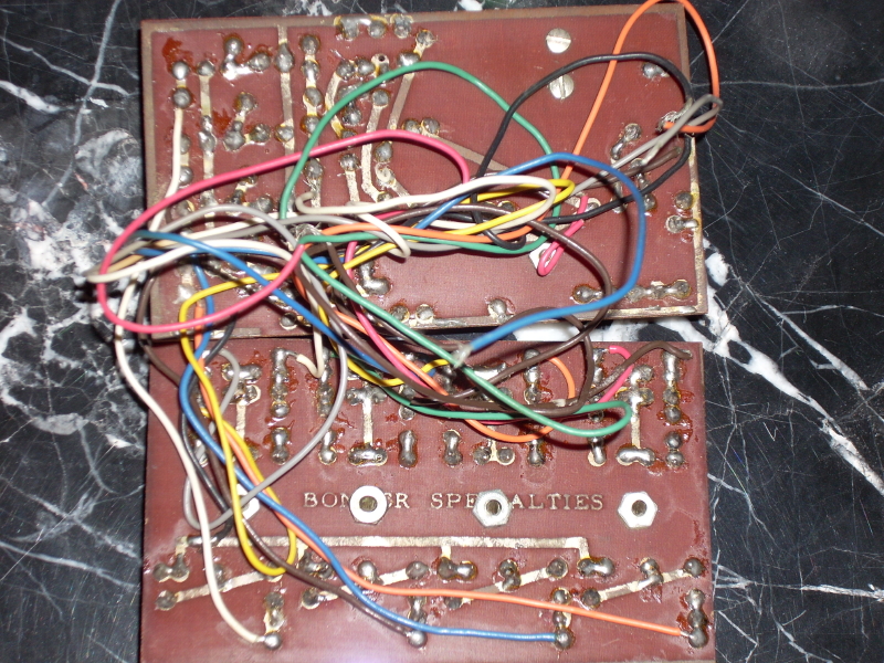
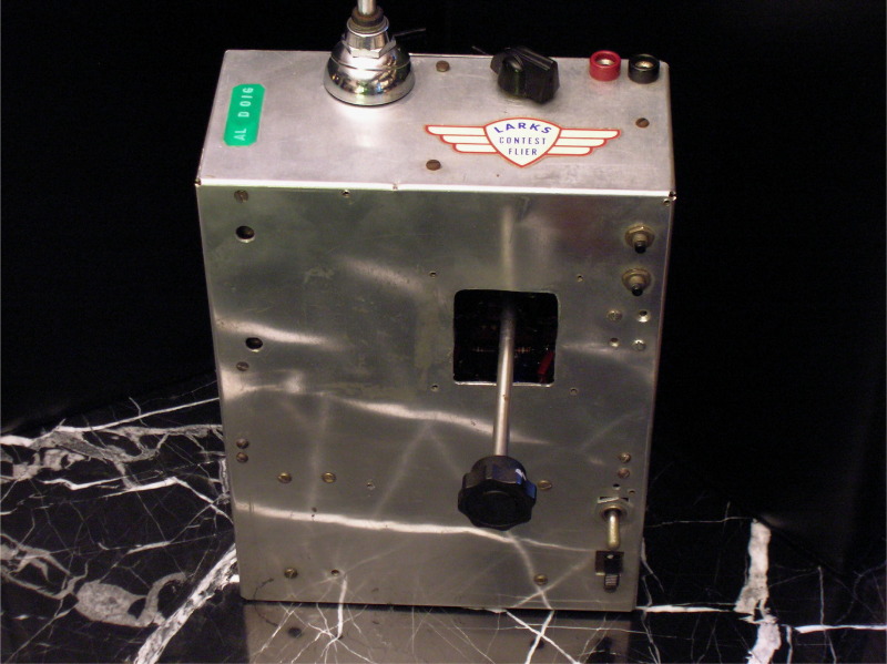
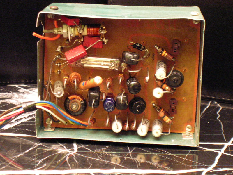
Notice that the servos and transmitter are identical with those shown in the May, 1959 article. The transmitter still has Al Doig’s identification tag on top. The receiver is his 4 channel multi version shown in the second article on the Ulti in July, 1959. Another receiver we have is a later version with “Ulti III” inscribed on it as part of the circuit board. This was presumably Al Doig’s third attempt, or generation, “Ulti” receiver.
The Ulti Multi was never produced for sale. It was published to inspire modelers to perfect and improve the concept. In the second article in July, 1959, Doig said this proportional program is in a “development stage” and “strictly experimental” but “maybe with more hands doing the work, correcting the mistakes, simplifying the design, and contributing new ideas, we will soon have the ultimate in multi”.
Historic Milestone
Considering all the industry heavyweights who were captivated and influenced by Doig's Ulti Multi is one way to appreciate its milestone importance in radio control history.
Doig certainly succeeded in inspiring others. We suspect most aspiring RC experts of that day were motivated by these articles to attempt their own Ulti Multi and touch the Third Dream of Radio Control. We have already discovered eight of the top RC engineers who did so:
Bob Elliot;
Sid Gates;
Frank Hoover;
Frank Kagele;
Gordon Larson;
Vernon MacNaab;
Jim Oddino; and
Carl Schwab.
Sid Gates was the head of Royal Electronics. Kagele and Larson designed the historic Bonner Digimite and were actually brought together by their attempt to get parts for their Ulti Multis. Jim Oddino was a championship RC contest pilot and author who went on to design and sell his own RC line, S&O. Carl Schwab designed Don Brown’s Quadruplex, the most reliable of all pioneering proportional systems. Bob Elliot developed the famous Transmite relayless reed servo for Bonner and co-founded E.K. Logictrol, a major rc manufacturer.
Vernon MacNaab modeled Citizen-Ship's first attempted proportional system after Doig's Ulti Multi. In the April, 1960 edition of American Modeler, Citizen-Ship announced that it had extensively flight tested a single channel feedback proportional system "quite similar to the Doig Ulti except that relays are used to control the servos."
The impact and influence of Doig's Ulti Multi were so profound that 6 years later (an eternity in electronics development) Carl Schwab and Don Brown called their new Quadruplex CL-5 system the "Ulti Ulti" ,with pride in how it overcame Doig's intermodulation problems (see below).
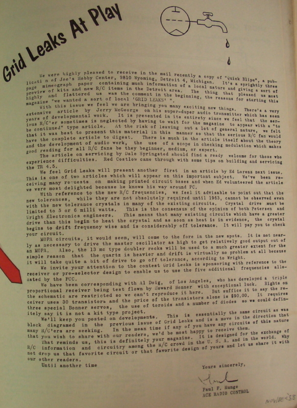
Doig’s achievement is even more remarkable when you consider that California RC'ers were generally hostile to proportional. Doig mentions in the article how “California has long been the hold out against proportional control” but that many California reed stalwarts actually fly “nervous proportional” by manually blipping or beeping the controls.
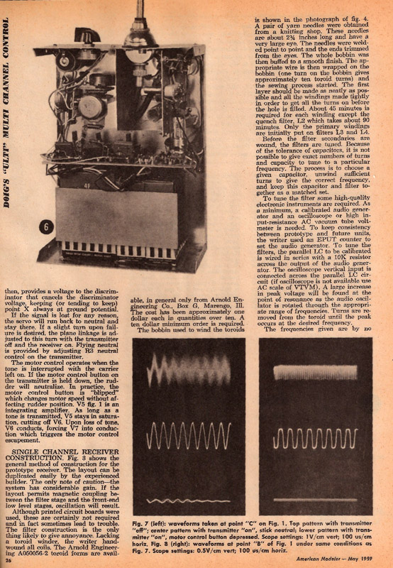
As a trailblazer Doig had to wind his own torroid coils. His article explains how to make a crude winding machine out of sewing needles and then wrap the coils with mylar tape. He called this process “tedious”.
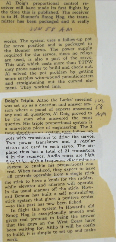
For servos he expertly fashioned new cases for Bonner “Boxcar” servo mechanisms but one inch longer to allow room for the amplifiers. He installed linear pots he made by heating purchased pots until they nearly melted and could be flattened. The transmitter was made to be exactly the size of the local Orbit 8 channel reed transmitter and was topped with a car antenna from a nearby auto parts store.
FIRST PROPORTIONAL?
Is it true the Ulti Multi was the first real proportional system? Some think there may have been earlier systems, based on their own recollection, or accounts they heard from others. However, individual memories are notoriously subjective, fading, sometimes self-serving, and unreliable. Urban myths also abound, where the story is often "improved" with each telling. What's special about Doig is that published accounts document successful ULTI MULTI flights in mid -1958 with both U.S. and Canadian witnesses. Earlier "proportional" systems had been flying for years, of course, most prominently Walt Good's TTPW, but these were not full-house, and/or were mechanical or interactive (Galloping Ghost or Kicking Duck) or entailed dithering, surface fluttering during normal operations , or other limitations.
 |  |  |
If the above accounts documenting how this may be the the first proportional system are not enough to provoke thought, see Epilog below. Newly discovered evidence suggests radio control history may need to be revised again.
Bonner And Doig
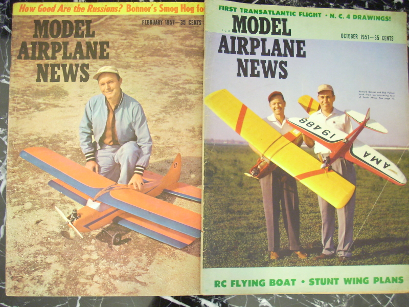
Bonner didn’t mind. He was thrilled just to be given the chance to fly such a “dream” radio control system. Five years later he repaid the favor. In 1964 Bonner’s 8-channel Digimite was the new dream eagerly anticipated by flyers worldwide. Prototype Digimites won the 2 top contests at the 1964 Nationals. With release of production models many months away, leading flyers begged Bonner for one of the prototypes. One man didn’t have to beg. Months before the release of production Digimites to the public, Bonner gave one of the coveted prototypes to Al Doig. It is now on display in our museum. See “Prototype Bonner Digimite”.
Additional Technical Information
By: Carl Schwab
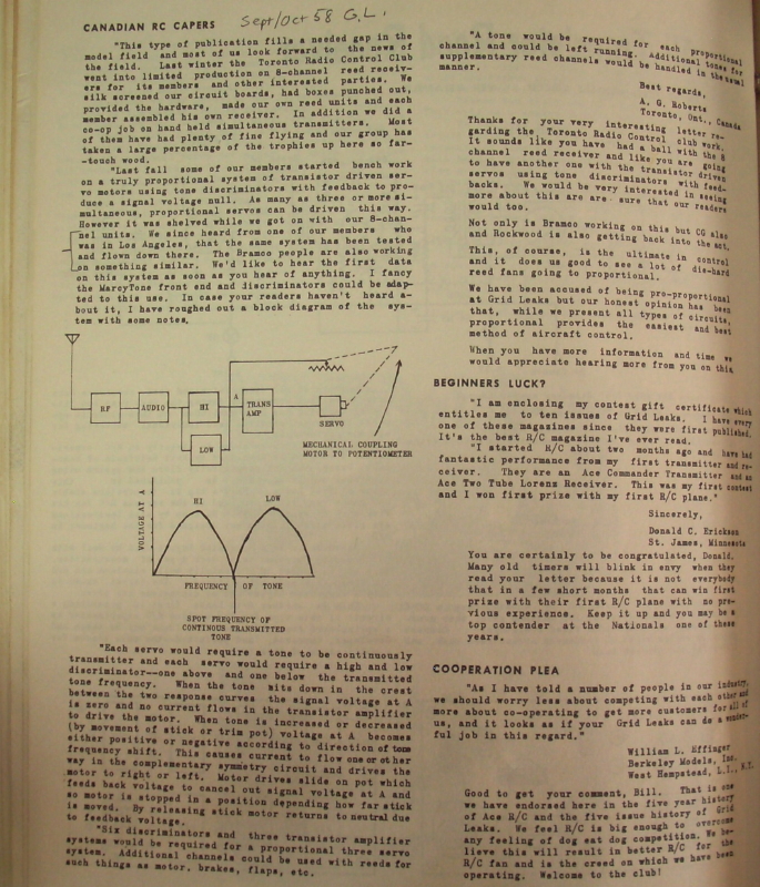
The system was pure FDMA (Frequency Division Multiple Access). It employed up to 4 subcarriers transmitted simultaneously. Given in the article are the coil frequencies for a 2-coil discriminator for each channel and are listed here. Rudder coils were tuned to 9120Hz and 8520Hz; elevator coils were tuned to 7625 Hz and 7025; aileron coils were tuned to 11,068Hz and 10,068Hz and motor coils were tuned to 5284Hz and 5884Hz. Thus separation for rudder was 600Hz, elevator was 600Hz, aileron was 1,000Hz and motor was 600Hz.
The transmitter was a tube design in the RF portion and transistor in the subcarrier circuits. Subcarrier frequency was determined by a “Twin Tee” arrangement. As much as I can determine the motor channel was not operated using a feedback servo but rather used two or three specific frequencies within the 600Hz range for either high or low motor and was switch selected. Also notice that the motor frequency range is ½ that of the aileron and comment is made “—when the low-speed motor button is depressed, no aileron movement occurs”.
Compared to analog proportional that followed, the Ulti-Multi was a straightforward, simple system. But it had limitations because of the intermodulation effects due to simultaneously transmitted tones and using hard limiting on the tone signals driving the discriminators. Also it had a weight penalty in the receiver (where it counts) in requiring 2, high quality coils for each discriminator. The AMA had just gotten approval for the 5, 27 MHz spot frequencies in addition to 27.255 MHz and it was understood that tone modulations were to be confined below 5 KHz. Clearly Doig’s system would have to be re-worked to lower the subcarrier frequencies if it were to be sold commercially on 27 MHz making the coil weight even heavier. But, nonetheless it was a definite step forward.
EPILOG