


Special Exhibit:
First Space Control
(Click on any of the images on this page to see a larger version)
The Space Control system made history as the first, commercially available proportional . This is the first Space Control ever made. It was produced by Solidtronics Corporation in late 1959 or early 1960 (probably the latter).
It led the way into a brave new world of proportional control.
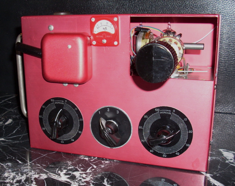
The First Space Control.
From its first public debut, Space Control was denounced and shunned by much of the manufacturing and flying establishment, but hailed by some commentators as the wave of the future. History would prove the commentators correct. Follow this link for the full story of the historic Space Control system.
Fatal Flaw
Since Solidtronics was designing the first commercial full-house proportional, no one knew where to put the throttle. There are no rules or standards to follow when you’re first. Moreover, the inventor, Hershel Toomim, had never flown reeds, or single channel or any radio control models at all. He started his RC career at the top, actually way above the top, with the most advanced system on earth.
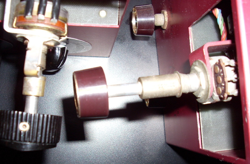
Solidtronics was a relatively large Company with specialized employees to handle mechanical, versus electrical, tasks. Thus, the throttle location may not have been Hershel Toomim’s decision. Regardless, as pioneers, exploring new territory, they can hardly be faulted. In retrospect, however, it is hard to imagine a worse throttle set up. As Solidtronics and other manufacturers later learned, a single stick proportional (right hand pilot) was best cradled in the left arm so the right hand could grasp the stick and the left could operate the throttle on the right hand side, or top, of the case.
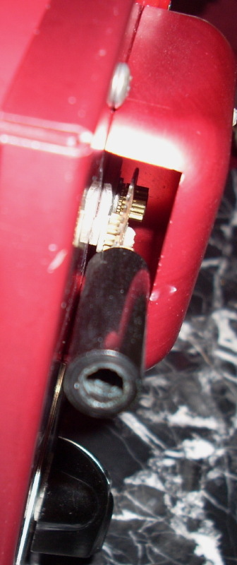
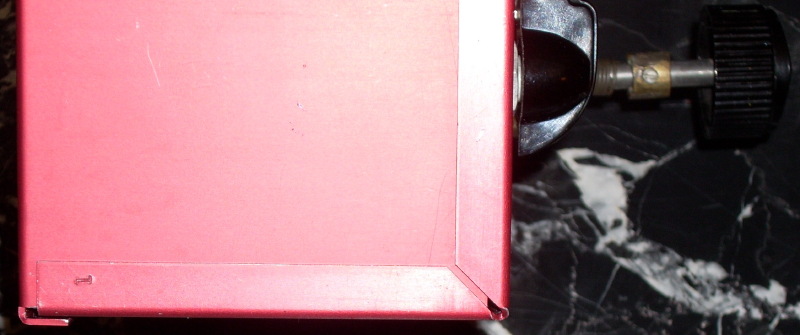
Logically, if a geared lever throttle were part of the design, and not a correction added later, it would have been installed inside the case where it would look better and could be located in a more ideal position. As for evidence, we found that every opening and hole in the case, including every screw hole, was cut or drilled before the case was anodized, except for three. This was standard industry procedure, done so the holes would be anodized too.
Three of the screw holes, however, were found to be raw aluminum color inside, indicating they were drilled through the anodized case at a later date. Two of these were for the bolts holding the lever/gear mechanism and its cover (the third was a modification to secure the RF shield as described under Differences below).
Thus, it may be assumed with some degree of certainty that #1 was designed to have, and in fact had for a time, only a single knob to the left of the meter for throttle operation. The 270 degree rotation of this knob and pot would have necessitated using two of the left hand fingers for reliable operation—fingers needed to hold the case.
The addition of the lever and gears reduced the required movement and facilitated operation. It was now possible to manipulate the throttle with the left thumb while holding the transmitter with the rest of the left hand and stabilizing the right side of the case with the right pinky. This was a clear improvement over the single knob throttle, but it would still have been highly awkward and impractical.
That’s why we believe it is quite possible this radio was never flown; especially since we now know that experienced RC pilots including Don Mathes also worked at Solidtronics and may have vetoed this throttle design almost immediately after they saw it.
Press Review
There is some evidence Space Control #1 was actually shown to the modeling press. In August of 1960, before any Space Control ads had run, American Modeler published a new product announcement with a favorable review. There was no picture, unfortunately, but one of the positive observations on the new system was:
“…the control sticks in the transmitter seemed real smooth and movement gradual…”
Was this a typo and American Modeler meant to say the “control stick” not “control sticks”? Or did the magazine get it right and they actually saw Space Control #1 with its second stick (for throttle) sticking out to the side? One reason to believe the latter is that it would explain why Solidtronics took the extra time and expense to have the case anodized with an attractive red finish. Anodizing would not be necessary if this were merely a prototype, never intended to be viewed by the public.
Observations By Others
Hershel Toomim recalls virtually nothing about Space Control #1. When first informed of its discovery he doubted its existence. Until he saw the pictures. He now confirms it was made by Solidtronics and precedes all known Space Controls. He proffered one additional, somewhat surprising, explanation for not remembering this milestone radio, beyond the two obvious ones—its brief service life and the passage of half a century! Hershel explained that Solidtronics was a relatively large company making many products and it would use its in-house specialists to do the mechanical and electrical work in building a prototype or production model, not him.
Vintage RC guru Ed Rutherford confirms this is a pre-production prototype and was professionally built prior to any known Space Control. Rutherford correctly surmised that the lever throttle was a subsequent addition before we found the physical evidence supporting this theory. He also believes there may have earlier been a simpler 6 tube circuit board, in the same case, with only a reed-type toggle switch for throttle.
RC electronics wiz Jay Mendoza used component date coding to determine the earliest date Space Control #1 could have been made—September, 1959. For over a year, Mendoza has been working with Zel Ritchie himself on Space Control matters, and his insightful conclusions warrant setting forth in full here:
“An analysis of this system is that it was the first attempt to build a working hand held transmitter version of lab developed bread board test circuits. The use of printed boards is the protocol for this phase when production is the intended goal. This first iteration proved out the layout, and stability of the circuit for the first time on reproducible medium, the printed circuit board. The board was compact enough to be mounted in a hand held case complete with batteries to serve as a working model for test and evaluation. Although the throttle, trims, and on/off switch layouts proved impractical, as did the two non removable peanut tubes, the basic design worked and served it’s purpose as an evaluation model. Due to the above noted issues that were revealed by this evaluation model, and any other electronic performance issues which we have not been able to test it for to date, this model may not have been flown. Its condition is such that it appears unused. The stamping “1” leads one to wonder if there was more than one made, but the chances are highly unlikely as this version has never been in any literature or publication until today, and it bears no model name or company logo. All other known existing Solidtronics are not only different, but bear the company logo and Space Control name, making this #1 a truly unique first version. It quickly revealed what needed changing and that was refined yet a third time when Zel Ritchie became involved, which is another story…”
The Big Surprise
It appears that no one alive knew this earlier model Space Control existed. Not even its owner. Not even after he gave it to us.
It was one big surprise.
The First Space Control was donated by Dan Garrabrant. Dan worked at Solidtronics for a mere 13 months. But in this short period he was a witness to history and a participant as well. He helped with everything from their Walkie Talkies to their talking dolls.
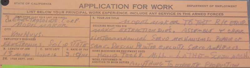
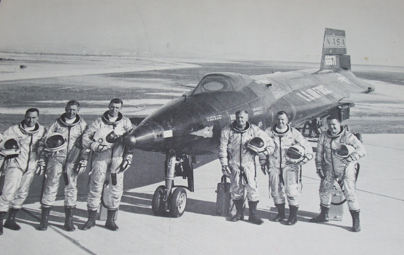
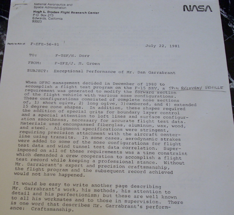
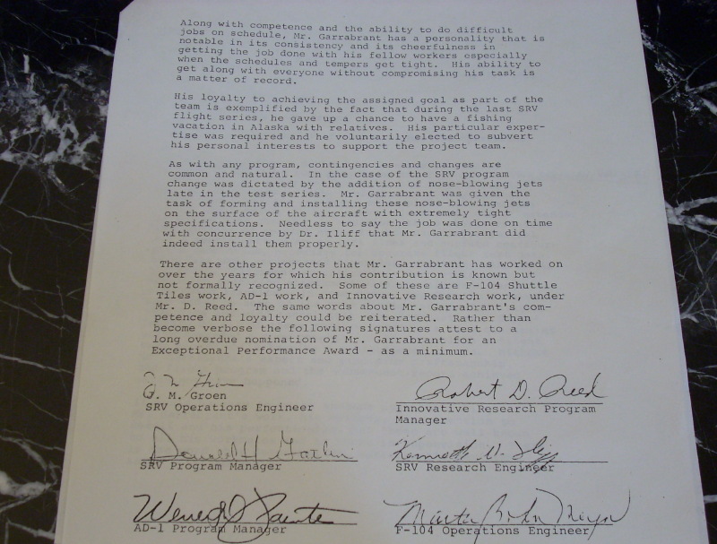
How good was Dan Garrabrant? Just ask NASA:
After learning about the Radio Control Hall of Fame, Dan decided to donate his sole souvenir of the Space Control program. He said he had kept all these years one brand new aluminum case from a Solidtronics Space Control that had never been assembled. Then, just before shipping he called back and said he opened a box next to the case and was surprised to find a new set of electronic “innards” for a Space Control which he’d send as well.
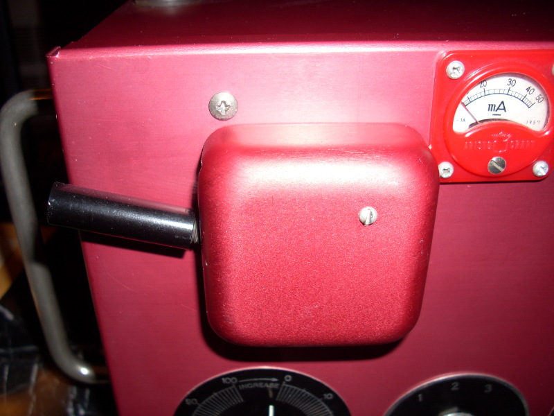
When we unpacked the case we were very disappointed. Someone had ruined its appearance by attaching an ugly bulbous lever device to the left side. We also discerned 3 faint circles on its front, where the anodizing was a deeper (unfaded) color, proving something had been mounted there for years and it wasn’t new and unused after all.
Then we opened the box.
Incredibly, it contained every single component necessary to complete a Space Control right down to the fasteners. Everything had been carefully disassembled and organized in the box for future reassembly. On top were 3 graduated discs which exactly fit the anodizing circles on the front of the case. All the other parts mated with the case perfectly as if they were made for it.
They were. We quickly realized we had something much more special than a new radio case. We had an entire Space Control, nearly new, but unlike any other ever seen.
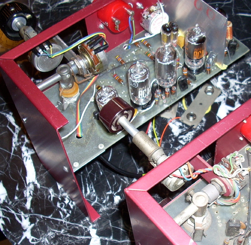
Peanut Tubes
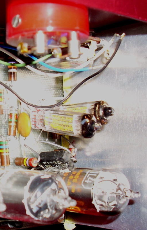
At first we speculated the peanut tubes were a subsequent add-on to a 3 channel system, to provide proportional throttle. Other manufacturers, like Kraft and Min-X, started with a 3 channel proportional with mere trimable throttle and then realized they needed proportional throttle to be commercially successful. In fact, the mounting holes for the throttle on Space Control #1 are consistent with there having been only a reed-like flipper switch there originally.
However, Hershel Toomim recalls that his system was always a four channel. He believes it could have never had 3 since, by design, it was comprised of 2, 2-function circuits he invented (and published) in 1937! Two times two is always four. He has no trouble explaining the peanut tubes. Tubes were expensive then and he had a fairly large supply of high impedence peanut tubes that he “inherited” from his previous employer. He used these in various Solidtronics projects until the supply ran out.
Differences Vis Production Models
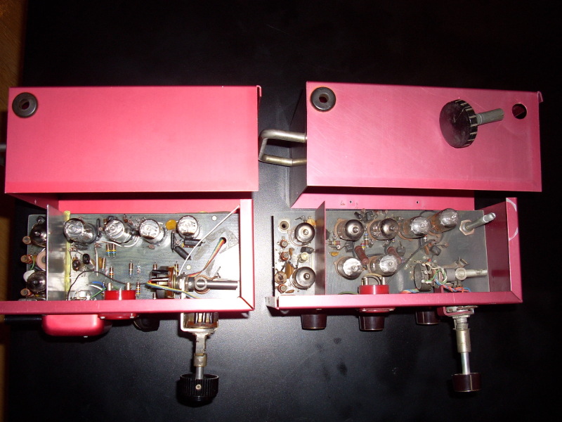
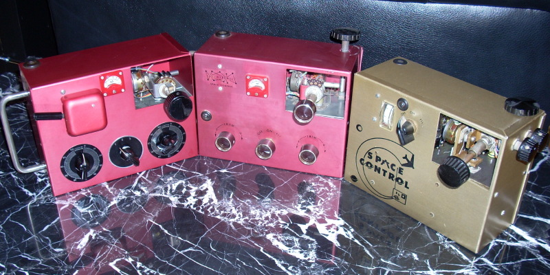
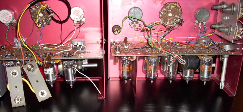
Here is a list of the differences between #1 and all other Space Controls, along with comparative photographs. In each photo comparison, the unit on the left is #1 and on the right a production model:
---Lever throttle on left with not even a hole for throttle in the case on the right. The corresponding hole below in the circuit board (which holds the throttle pot in all production models) is also absent.
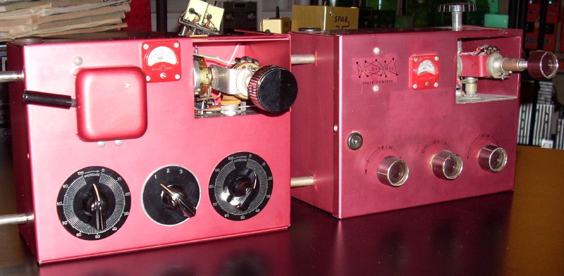
---Large, black circular position indicators behind the lower 3 knobs.
---All knobs different.
---No indicator light.
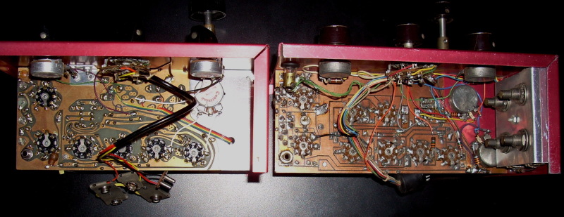

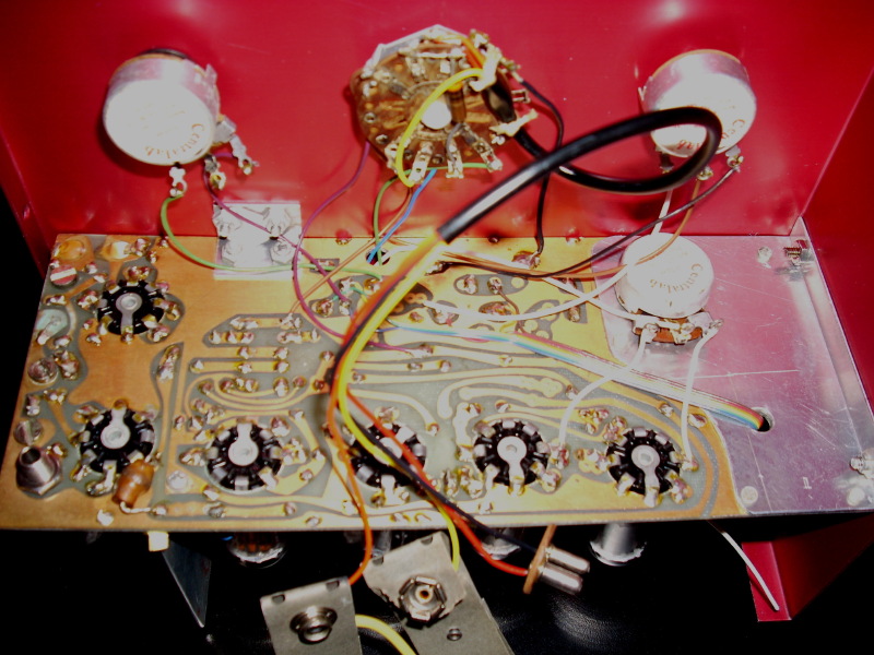
---Circuit board mounting brackets and RF shield all different in shape and attachment, and not anodized.
---Same gimbal “L” bracket.
---Same red plastic case Aristo meter, but different location.
---Gimbal cut out somewhat larger and mounted closer to edge; no “lip” above or on right.
---PC Board mounted in case about 3/8 inches higher.
---Handle location slightly different.
---RF shield bolted to circuit board and secured through front of case with single bolt, versus riveted to board and secured to front of case with 2 metal screws on production models.
---All parts, even meter, attached with machine screws and special aluminum retainer nuts, plus separate brackets, instead of simpler, less expensive metal screws. Screw holes in case sized differently for this purpose.
---Wired for 3 dry cell batteries.
---#1 Has same Solidtronics-red anodizing, shades different from other manufacturers’ red anodized cases (e.g. Citizen-Ship, Logictrol).
