


Special Exhibit:
Paul One
(Click on any of the images on this page to see a larger version)
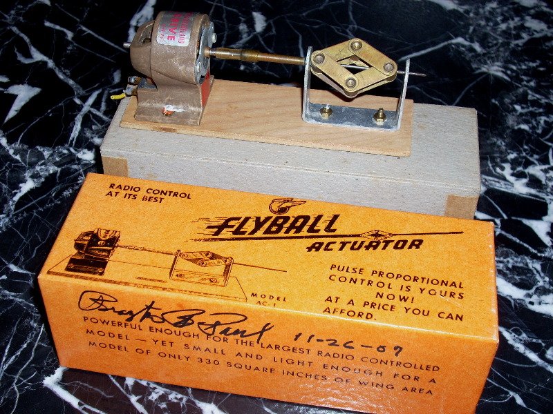
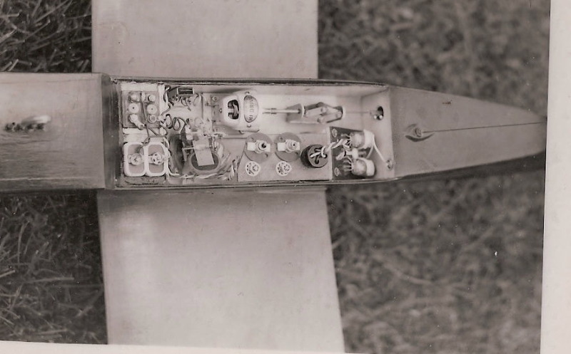
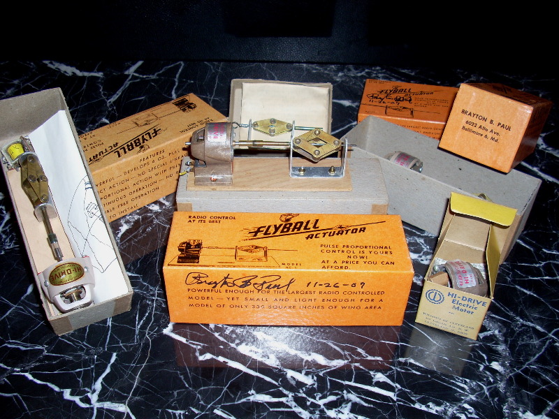
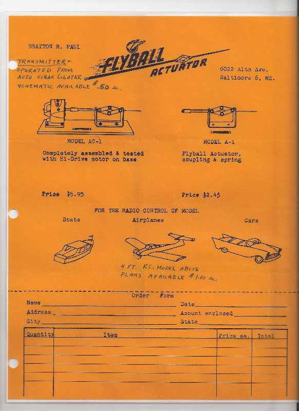
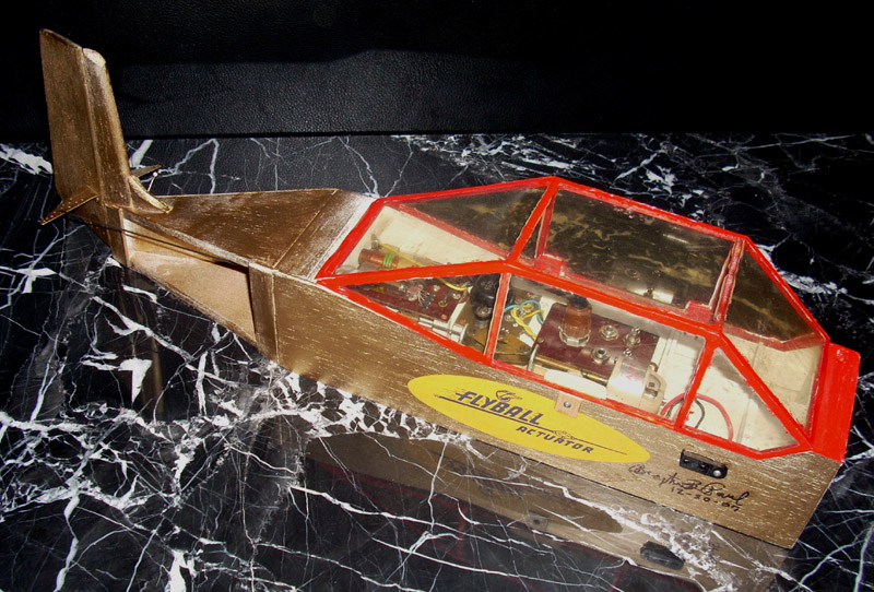
This was Brayton Paul’s personal Flyball Actuator. Fly What?
Throughout history, technological advance has been driven by individual inventors able to think outside the box. In 1951, Brayton Paul came up with an ingenious device for converting radio signals to push-pull motion capable of controlling flight surfaces. He harnessed centrifugal force to overcome limitations of period escapement actuators and earn his place in radio control history.
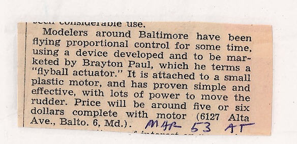
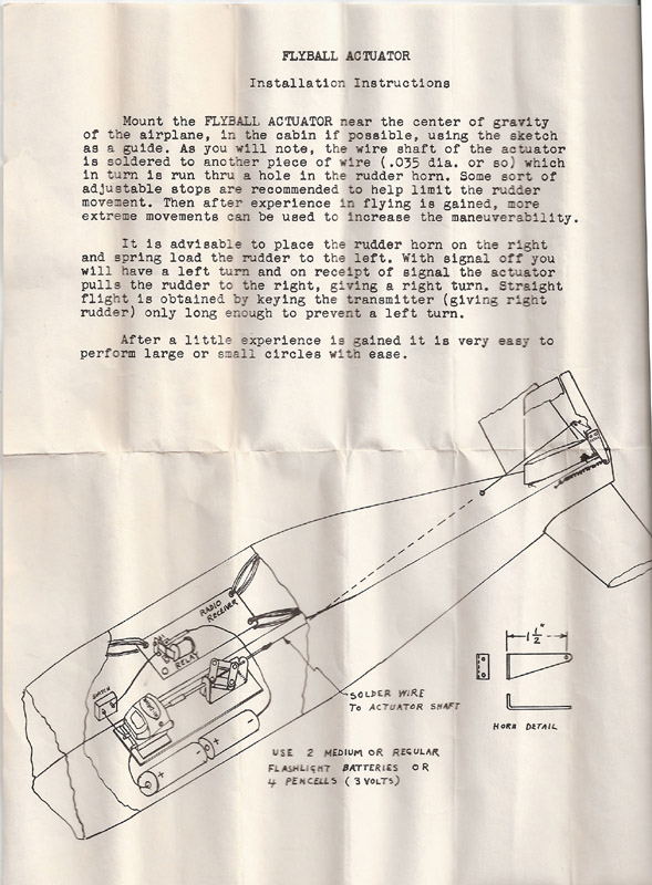
In the early days of radio control, pilots were essentially interrupting or modifying the flight paths of free flying models. When pursuing this “First Dream of Radio Control” they too often had to watch their ships destroyed or fly away after radio failure at some point in the system. These experiences motivated Brayton Paul to develop a “one-way actuator”. If the radio failed, the rudder would automatically go to the opposite side and the plane would circle down (normally ending in a crash).
Paul reasoned it was better to carry a broken model home than to bring back nothing; and he believed his design had other advantages over rubber-powered escapements including its not needing critical adjustments and being unaffected by vibration and wear. Other advantages were the actuator’s increased thrust due to the mechanical advantage of the mechanism, its quick response time, the ability of the motor to start with no load, thus minimizing battery drain, and the negligible loss in motor RPM under load.
The Flyball Actuator was inspired by two industrial predecessors. The first was a rotary telephone governor Brayton Paul saw in Europe during World War II, and the second was the “flyball governor” used to regulate steam engines for over a hundred years. From the latter device the Flyball Actuator took its name. The RC flyball, like its ancient steam engine ancestor, employed a centrifugal expansion mechanism to produce a linear motion used to achieve its purpose.
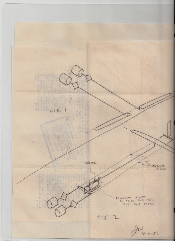
The Flyball Actuator gave a linear pull each time it was caused to spin by keying or pulsing the transmitter. This motion was used via a wire rod to pull the model’s rudder way from the default left rudder position to varying degrees, including neutral and full right rudder, depending on how long the pilot gave the command. When the pilot ceased commands, the rudder was pulled back to its left default position by a spring. With practice, and a small rudder area, it was fairly easy to achieve straight flight and very easy to execute turns (which, to this day, comprise most of an R/C model’s flight anyway).
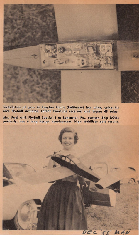
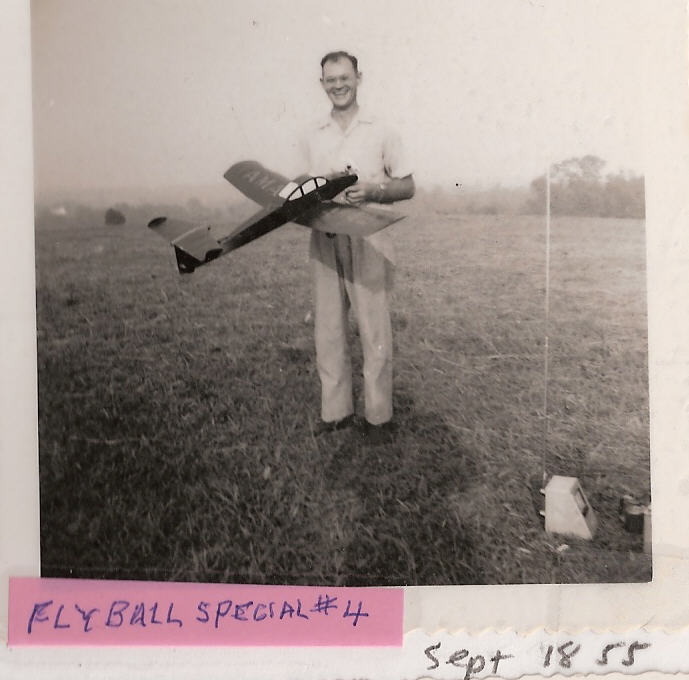
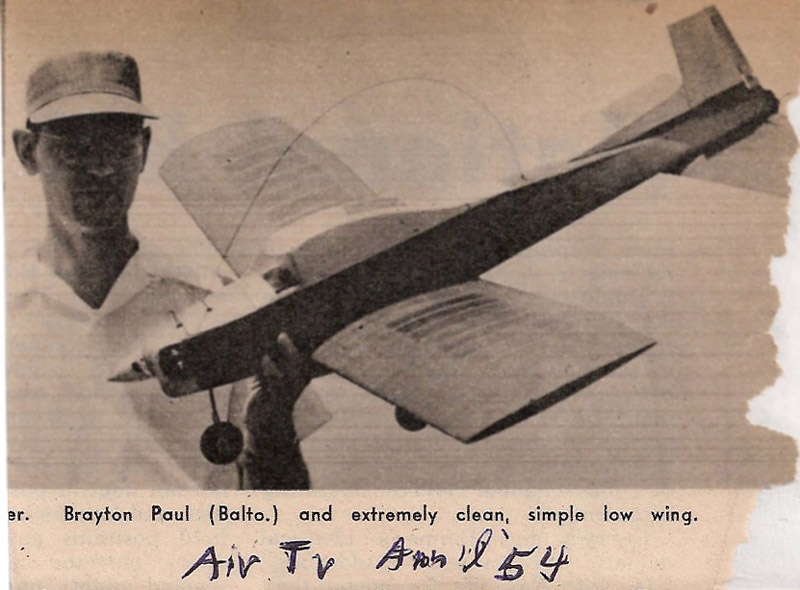
Here are pictures from the December 1955 Model Airplane News showing Mrs. Paul with one of Brayton’s signature low wing ships and his Flyball Actuator inside. Note that a slightly older drive motor with an oval label was still on it at the time of this picture:
 |  |  |
Here are some additional examples, from our museum, and one of the Hi-Drive motors he used, made by a Cleveland, Ohio company.
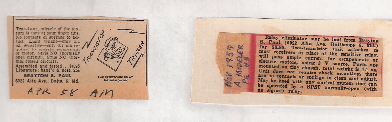
Brayton Paul and others flew their Flyball Actuators for years, but the system had a weak link that bothered Paul. The Sigma 4F Relay was subject to vibration and required delicate adjusting for the low power output of the receive. Finally, in 1957, he found the solution.
He saw an ad for CBS Power Transistors with circuit diagrams and components for a solid state, transistorized relay. Before long he devised the Transistor Trigger.
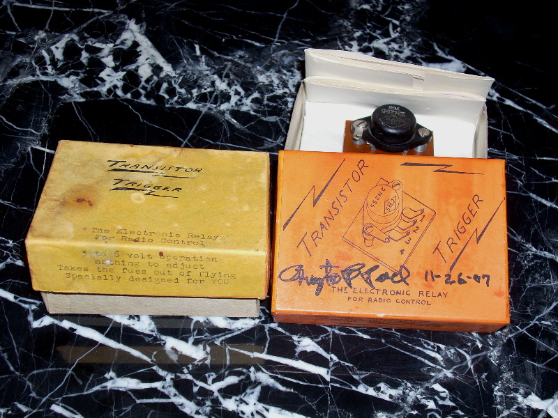
Brayton Paul’s journey through radio control development had come to its end. The combination of a two-tube receiver, Flyball Actuator and Transistor Trigger gave him the positive control he had so long sought.
