


Special Exhibit:
Controlaire Three Channel
A Mystery Including a Ghost from the Past
(Click on any of the images on this page to see a larger version)
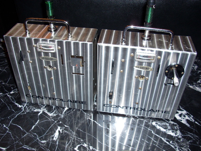
These are the first Controlaire three channel proportionals ever made. They were prototypes, built around 1968, to explore the concept of a more affordable 3-channel alternative to Controlaire’s full house proportional. Ultimately, Controlaire decided to pursue the M.A.N. 2-3-4 for its budget line, and the three channel models may never have been produced. These two prototypes were the first, and maybe the last, of their line.
The Controlaire Three Channel.
After Don Baisden took over as Chief Engineer (see “First Controlaire Proportional”) it became Controlaire’s practice to produce 2 prototypes of each new model. One would go to Baisden for his personal use and flight-testing. The other would serve as the model for refining and staging full-scale production. The prototype with the O.S. stick was Baisden’s. 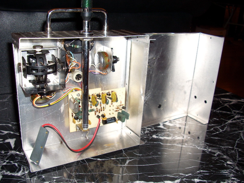
The other one was made for an O.S. stick but, although otherwise completed inside, the stick assembly was never installed. The four stick assembly retention screw holes are new inside without any marks from bolts or screws being threaded or passed through. Controlaire’s three-channel program was abandoned before reaching the need to mount the control stick in this one.
End of story? Hardly.
The Controlaire Three Channel story is not as simple or clear as the previous paragraphs imply. There is also an historical oddity cloaked in at least a little mystery. Years before these “first and only” three channel transmitters were built, Controlaire ran an advertisement for a three channel digital proportional. What?
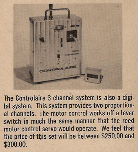
Note that this 1965 system was to have only two proportional channels, not three like our prototypes. The third channel was to be a trimmable throttle operated by a reed-type toggle switch. So, at a minimum, our two prototypes continue to be the only true 3 channel proportionals ever made by Controlaire. Moreover, we suspect the pictured 1965 “three channel” wasn’t real, but only a ghost, and a galloping one at that. Research continues, but at this juncture we believe the pictured 1965 “3 channel system” was a mere mock-up and none were ever produced or even prototyped.
It was fairly common back then for manufacturers to prepare ads for systems which weren’t finished yet due to the long publication lead times. Sometimes a planned system was never produced (or even prototyped) leaving only the advertisement with its then-misleading message.
Rutherford made this after finding a rare, first-generation, open-gimbal Controlaire Galloping Ghost for a pittance. The reason it was so cheap is the case was almost entirely destroyed. Rutherford had a new, empty case from his days as a Controlaire dealer and he simply mounted the undamaged insides into the new case.
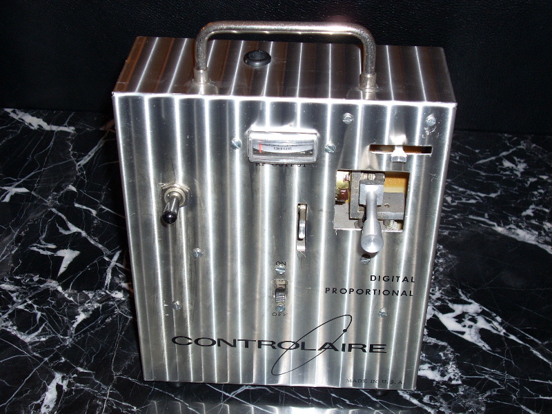
Ed Rutherford knew this would result in a genuine Controlaire Galloping Ghost, just like those originally manufactured, if he took one more little step. All he had to do was glue a standard Controlaire Galloping Ghost plaque over the words “DIGITAL PROPORTIONAL”. He recalled how all Controlaire proportional and galloping ghost transmitters started with the same case for commonality savings. All cases had “DIGITAL PROPORTIONAL” printed on them and those that became ghost transmitters had the plaque glued over these words at the factory.
Thus, it couldn’t have been much easier to produce the 1965 three-channel mock-up. We suspect they simply used a galloping ghost transmitter without the plaque. The result would look like the purported three-channel proportional pictured in the ad, including the black flipper switch on the left side.
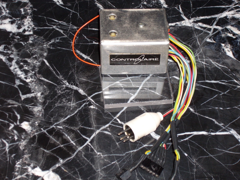
End of story? We wish. But it isn’t going to be that simple. Look carefully at the portion of the transmitter case immediately above and below the on-off switch. And what about the pictured receiver?
Some mystery remains.
2009 UPDATE---NOT THE ONLY ONES
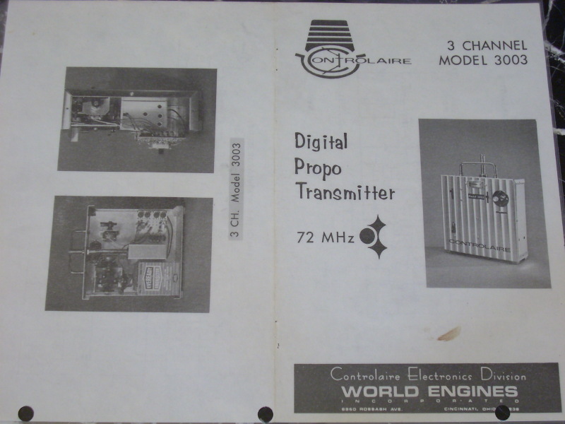
Months after publication of the foregoing account, Don Baisden found a brochure which conflicts with his recollection that no 3 channel proportionals were ever sold:
 |  |
 |  |
Since major portions of this brochure depict and describe 4 channel systems, not 3, it may have been a mock-up or prototype brochure never actually used. Baisden, however, guesses it was more than a mere draft. He says “This is what happens when you delegate.” He believes this brochure was botched, but probably used as is.
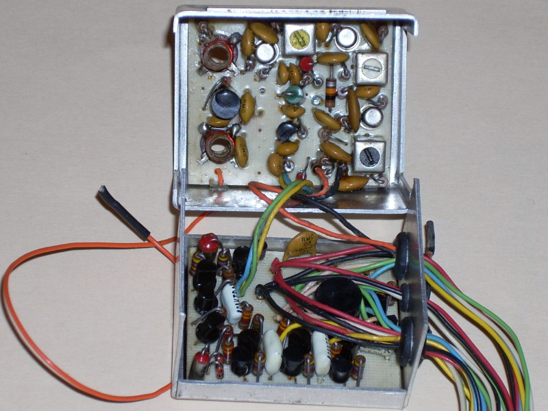
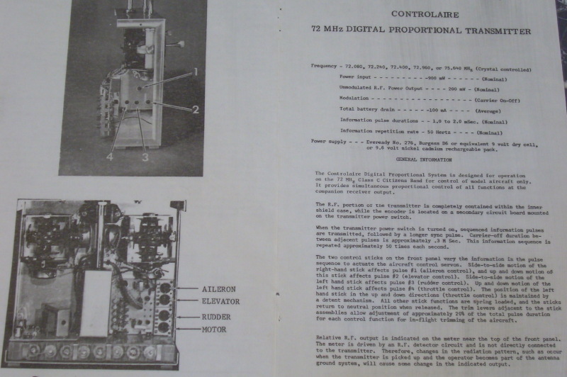
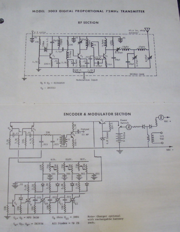
The brochure establishes, at a minimum, that at least one more prototype 3 channel was made. It’s a 72 Mhz version, which used a can to shield the RF module and no stub antenna out the back of the case. The stub antenna, seen on our prototypes, was a Controlaire trademark in earlier years. It was used to range check the transmitter, with the main antenna removed. Otherwise, the centerloaded antenna would produce excessive range for testing, even when collapsed.
The PC Board appears to be a full four channel unit with components for the additional channel simply not installed. This is consistent with numerous Controlaire ads in 1968 and early 1969. These ads pictured only the 4 channel, but separately described 2 and 3 channel systems as being available for less money. Some of these ads warned that the 2 and 3 channel versions would have only one stick and could not be readily upgraded to 4 or more channels. This may have suppressed sales.
Hence, our Controlaire Three Channels may have been the first, but it is unlikely they were the only ones. It is probable others were produced and maybe even some 2 channel digital proportionals. The main mystery then is: Where are they? Why havn’t they turned up yet in major collections? They should be out there, somewhere. Please let us know if you have one.
